
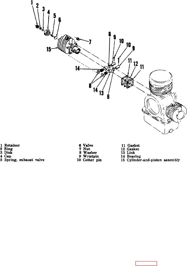
Figure 3-6. Third stage section, exploded view.
d. Assembly.
(4) Pull cotter pins (10) releasing wrist-
pins (9). Remove wrist-pins, washers
(8), bearings (14), and link (13)
Note. To measure and adjust piston-
releasing piston from rod.
head-to-valve-seat clearance, install
first or second stage cylinder-and-
Note. The cylinder and piston are
piston assembly to guide the cylinder
matched parts. Do not separate the
being measured and adjusted.
cylinder and piston or mix with
similar
components
of
other
(1) Place 25 needle rollers (14) around
compressors. Scribe small marks
edge of wrist-pin hole in one end of
third stage connecting link (13).
inside skirts to identify side of piston
Place link washer (8) at ends of needle
that was toward fan end of
rollers. Position connecting link inside
piston of cylinder-and-piston assembly
(15) and press in wrist-pin (9). Secure
(5) Remove gaskets (11 and 12). Record
with cotter pin (10). Use petrolatum
thickness of gasket combination and
discard.
(2) Assemble 25 needle rollers (14) and
two link washers (8) in wrist-pin hole of
Note. By measuring the thickness of
connecting link (13). Pass free end of
removed gaskets and adding 0.005
third stage connecting link (13)
inch for each new proper gasket to
allow for crush at installation, new
gaskets required to obtain proper
clearance can be selected with ease
during reassembly.
24

