
TM 3-1040-263-34
1
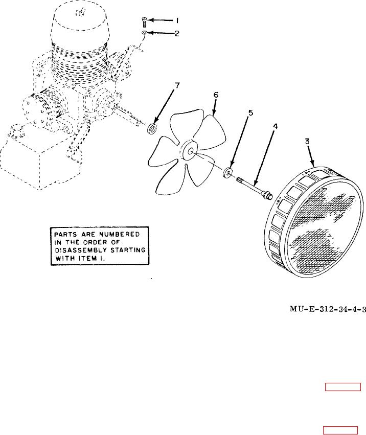
Screw
3
Fan guard
6
Fan
2
Washer
4
Machine bolt
7
Backup washer
Figure 4-3. Fan group-exploded view.
Section III. SECOND-STAGE RELIEF VALVE
b.
Remove protecting cage (para 3-7).
4-8.
General
c. Remove first-stage
strainer
and
filter
General support maintenance personnel are authorized
assembly (TM 3--1040-263-12).
to replace the second-stage relief valve.
d. Locate loop clamp (fig. 3-3) securing
CAUTION
second stage heat exchanger.
Cap or tape all openings after removing
e. Unscrew and remove nut (1) and screw (2)
components from equipment to prevent dirt
securing each clamp (3) to compressor.
from entering the openings.
f.
Disconnect second-stage heat exchanger
4-9.
Disassembly
from
the
second-stage relief valve and elbow.
a.
Remove canvas cover (TM 3--1040-263-
12).
4-4

