
TM 3-1040-263-34
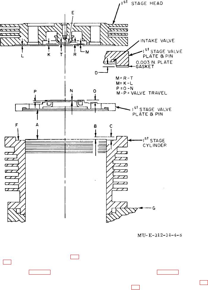
Figure 4-8. First-stage section valve travel and head clearance .
f Installation.
(1) Disconnect aftercooler end nut (8, fig.
3-1) from water separator elbow (19).
(2) Using the crankcase removal
(1) Using the crankcase installation
instructions (para 4-32a), remove
instructions (para 4-36), install
compressor from engine.
compressor on engine.
(3) Perform one-hour break-in run (para 3-
(2) Connect end nut on aftercooler (8, fig.
39) or four-hour break-in run (para 4-
3-1) to water separator elbow (19).
41).
4-15

