
TM 3-1040-263-34
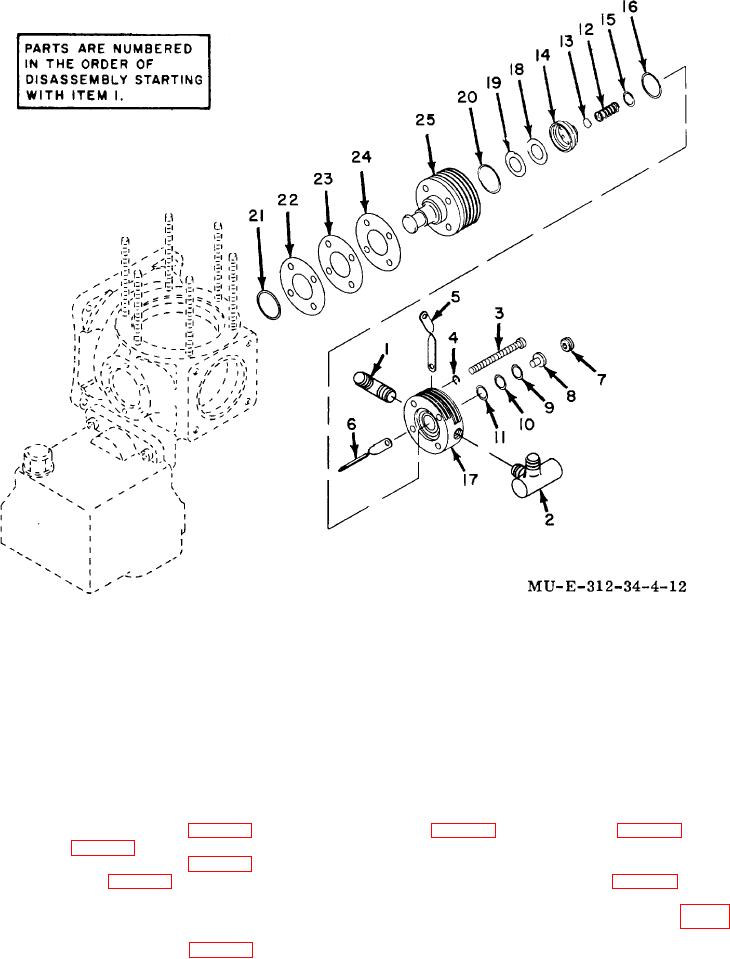
1
Elbow
9
Shim
18
Inlet valve
2
Relief valve
10
Shim
19
Inlet spring
3
Screw
11
Shim
20
Head gasket
4
Lockwasher
12
Outlet spring
21
Preformed packing
5
Cooler bracket
13
Outlet valve
22
Shim
6
Cooler bracket
14
Valve plate
23
Shim
7
Lockscrew
15
Plate seal
24
Shim
8
Valve stop
16
Plate gasket
25
Cylinder and plunger assembly
17
Head
Figure 4-12. Third-stage section-exploded view.
(1) Determine measurement 1 (fig. 4-14) on the
plate (14, fig. 4-12). Measurement 3 (fig. 4-14) should
third-stage head (17, fig. 4-12).
be within 0.000 to +0.001-inch of measurement 2 minus
(2) Determine measurement 2 (fig. 4-14) on the
measurement 1.
third-stage valve plate (14, fig. 4-12).
(5) Position outlet valve (13, fig. 4-12) on the
(3) Position the plate seal (15), plate gasket (16),
valve plate discharge valve seat.
and third-stage valve plate (14) on the third-stage head
(6) Determine measurement K and M (fig. 4-
(17) and press in until bottomed.
14).
(4) Determine measurement 3 (fig. 4-14) to
(7) Obtain result of MI minus K (discharge valve
travel). Select shims (9, 10 and 11, fig.
insure proper installation of the third-stage valve
4-21

