TM 5-4220-233-14
4-43. BRAKES.
This task covers:
a.
Adjustment
INITIAL SETUP :
Tools
Materials/Parts Appendix D
Screwdriver, Flat Tap
None
Equipment Conditions
None
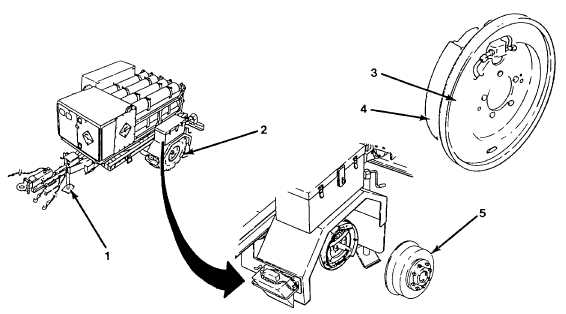
Figure 4-28. Adjust Brakes.
a.
Adjustment.
(1) Raise the Servicing Unit using the front and rear swivel jacks (1) until both tires are off the ground.
(2) Ensure handbrake is released.
(3) Spin each wheel (2) and verify that the wheels stop turning in ¼ to ½ revolutions. If wheels stop as
specified proceed to step 6, otherwise continue to step 4.
(4) Remove dust plug(s) on backside brake assemblies (3) and slightly turn brake adjuster(s) with a
screwdriver to increase or decrease brake shoe tension as required.
(5) Repeat step 3 and 4 until required adjustment is obtained then install dust plug(s).
(6) Spin each wheel (2) slowly and audibly check for brake shoe (4) to drum (5) contact through 360
degrees of rotation. If contact Is not as specified continue to step 6.
(7) Burnish brake shoes by towing the Servicing Unit approximately five miles and subjecting the unit to
frequent stops.
(8) Repeat step 3 through 6 until required brake shoe to brake drum contact is obtained for each wheel.
4-66