TM 5-4220-233-14
9
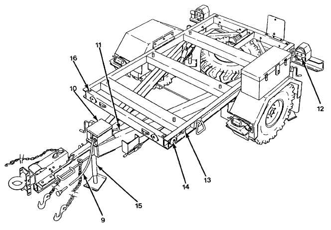
Intervehicular Cable. Provides the electrical interface between the towing vehicle and the trailer
Equipped with a standard 12-pin connector.
10 Electrical Box. A weather-proof junction box where the trailer wire harness is connected to the
Intervehicular cable.
11 Wire Harness. Distributes electrical signals to the trailer marker, tail, stop, turn and blackout lights.
12 Composite Light . Provides the rear tail, stop, turn, and blackout lights for the trailer.
13 Marker Light. Provide an outline of the trailer envelope. Red markers are mounted at the rear and
rear/sides of the trailer chassis. Amber markers are mounted at the front and front/sides of the trailer
chassis.
14 Reflector. Mounted at front corners and front/side corners of the trailer chassis. Reflectors are amber in
color.
15 Swivel Jack. One front and two rear jacks are provided to allow the Servicing Unit to be operated on
sloped terrain.
16 Circular Level. A bubble-type level that is used as a guide when operating the swivel jacks to properly
level the Servicing Unit prior to operation or maintenance.
Figure 1-3. Servicing Unit Trailer Assembly. (Sheet 2)
1-9