TM 5-4220-233-14
5-4 REAR AXLE
This task covers:
a.
Removal
b.
Installation
Tools/Test Equipment:
Materials/Parts (Appendix D):
Screwdriver, Flat Tip
Wiping Rag (Item 13)
Screwdriver, Cross Tip
Cleaning Solvent (Item 15)
Stands, Jack - 3 each
Container (Item 7)
Stands, Floor -2 each
Socket, 7/8”
Equipment Conditions:
Socket Wrench Handle, 1/2 Drive
Remove Hub and Drum Assembly
(paragraph 4-42)
Wrench, 3/8"
Remove Shock Absorbers (paragraph 4-45)
Wrench, 1/2"
a.
Removal.
WARNING
Axle is heavy and awkward to handle. Provide adequate support under
trailer chassis and axle at all times. Failure to follow this warning may
result in serious injury or equipment damage.
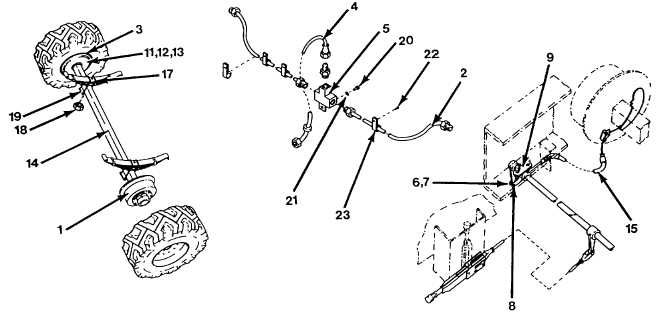
Figure 5-1. Remove Axle Assembly.
(1) Place an empty container below the brake assembly (1), then disconnect brake line (2) from
backside of brake assembly (1) and allow fluid to drain.
(2) Repeat step 1 for other brake assembly (3).
5-2