
TM 5-4310-227-15
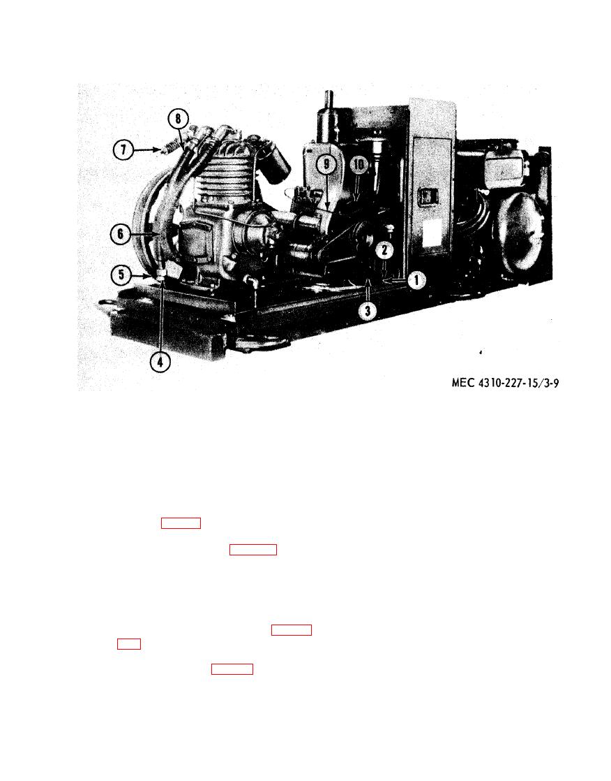
1
Nut
5
Adapter
9 clamp
2
Bolt
6
Aftercooler
10 Rim
9
Base
7
Unloader valve
4
Elbow
8
Elbow
(3) Remove the screws (19) and lock-
(6) Connect the spring (25) to the link
(1) and the governor control (27).
washers that secure the fuel pump
(43) to the cylinder and crankcase
(7) With the knob of the governor con-
trol (9, fig. 2-2) in the full in posi-
assembly (18) and remove the fuel
pump and gasket. Discard the gasket.
tion, place a slight amount of ten-
sion on. spring (25, fig. 3-10) and
b. Cleaning and Inspection.
tighten screw on link (1).
(1) Clean the exterior of the fuel pump
with a cloth dampened with an ap-
proved cleaning solvent and dry
a. Removal (Models BMW-452-ENG and
thoroughly. Be sure all gasket ma-
BMW-452-ENG-1).
terial is removed from the fuel pump
(1) Close the fuel shutoff valve (18, fig.
and cylinder and crankcase assembly.
2-6) .
(2) I n s p e c t the fuel pump for cracks,
(2) Disconnect the fuel pump - to - car-
evidence of leakage, and other dam-
buretor tube (9, fig. 2-7) and fuel
age.
strainer-to-fuel pump tube (41) from
(3) Replace a damaged fuel pump.
the fuel pump (43).

