
TM 5-4310-227-15
sembly (18) with the bolt (28), two
lockwashers (23) and nut (40).
(8) Secure the magneto to the bottom side
of the cylinder and cranckcase assem-
bly with the capscrew (22) and lock-
washer (23).
(9) Turn the engine crankshaft over slow-
ly by hand. If the magneto is proper-
ly timed, the impulse coupling will
snap when the flywheel air vane tim-
i n g mark (X) (2, fig. 3-12) ap-
p e a r s in the top center inspection
hole (4, fig. 3-11).
(10) Install the magneto drive gear inspec-
tion plug (14 fig. 3-2) in the crank-
case gear housing.
(11) Position the high-tension cable outlet
in the ignition shield (13).
(12) Connect the ignition cable to the mag-
neto (para 3-45).
(13) The proper spark advance is 20 per-
cent. For checking timing with a neon
light, the running spark advance is
i n d i c a t e d through the timing hole
(3, fig. 3-11) located 20 before top
center on the air shroud rim (5). The
1
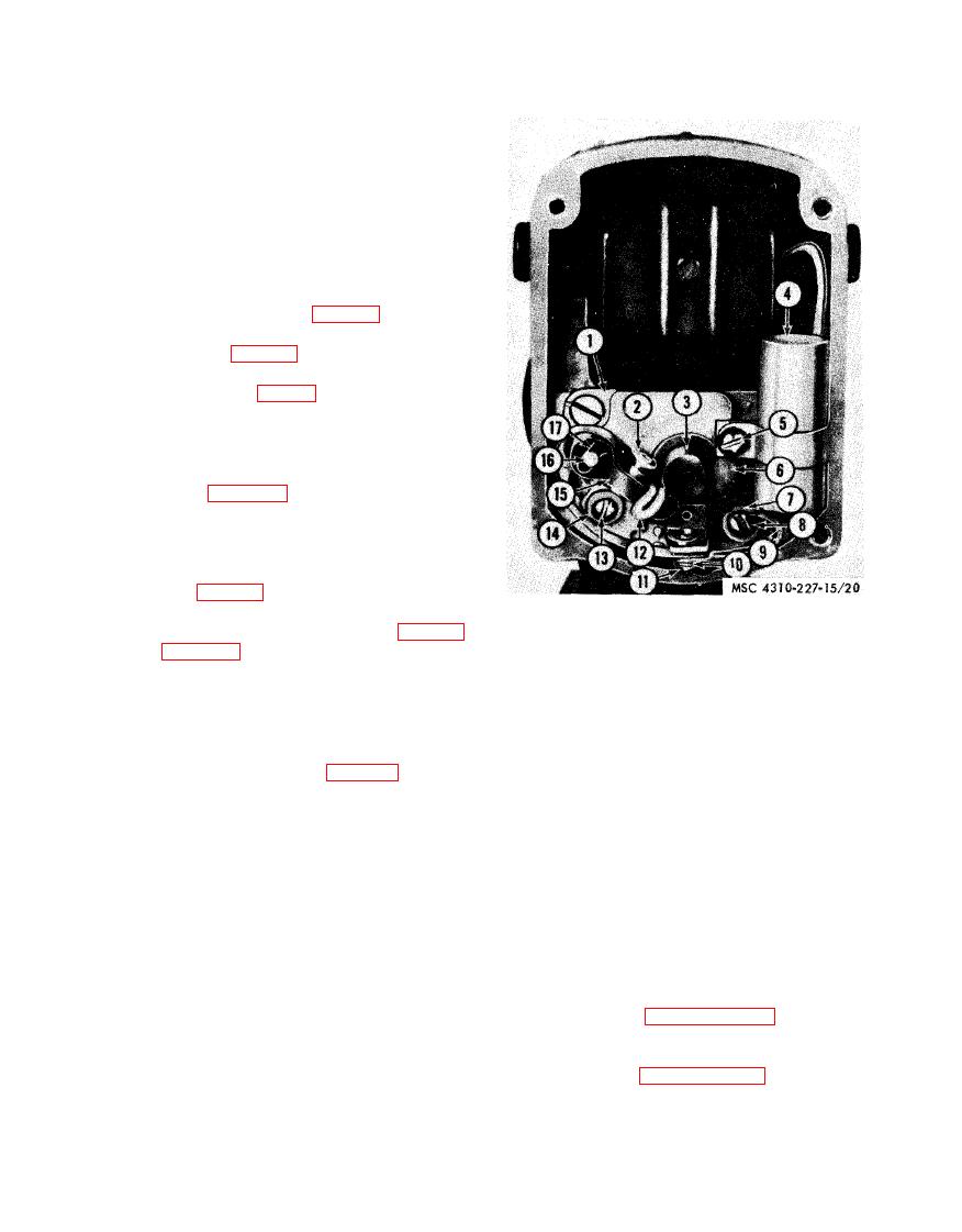
Bearing support plate assembly
air vane timing mark (X) (2, fig. 3-
2
Contact set support plate
Magneto rotor
3
paint for this operation.
4
Capacitor
d. Contact Set Adjustment.
5
Screw, mach. 8-32 X 1/4 in.
6
Camwick and holder assembly
(1) Remove the magneto ignition shield
7
Washer, flat, No. 8
(see (a) above).
8
Screw, mach, 8-32 X 3/8 in.
(2) Rotate the engine by hand until the
9
Lead
magnatic rotor (3, fig. 3-13) opens
10
Washer, lock, No. 6 (2 rqr)
the contact points to full separation.
11
Screw, math. 6-32 X 3/8 in.
12
Breaker arm flat wick
(3) Measure the gap setting of the con-
13
Screw, math. 6-32 X 3/8 in.
tact set by inserting a feeler gage be-
14
Washer, flat, No. 6
tween the breaker points. The proper
15
Breaker arm and spring
gap is 0.015 inch.
16
Fulcrum pin
(4) Loosen the contact support locking
Retaining ring
17
screws (8 and 13) just enough to al-
low movement of the contact set sup-
removal points.
port plate (2). Adjust the gap until
a light drag is felt as the feeler gage
(1) Remove the magneto ignition shield
is withdrawn.
(see a above).
(5) Tighten the locking screws (8 and
(2) Refer to paragraph 4-19 a (3), (4),
13) and recheck the gap setting.
and (5), for the removal of the con-
(6) Install the magneto ignition shield
tact set.
(see c above).
(3) Refer to paragraph 4-19 c (16), (17),
and (18), for the installation of the
e. Contact Set Replacement (Models BMW-
contact set.
452-ENG and BMW-452-ENG-1).
3-37

