
TM 5-4310-227-15
secure with the screws (1) and lock-
washers.
(2) Position the shock mount (5) on the
g e n e r a t o r and regulator mounting
b r a c k e t (8) and secure with the
screws (9) and lockwashers.
Note. Refer to paragraph 3-31 for the
proper placement of the tooth-type lock-
washers, ground lead, and capacitors.
(3) Connect applicable electrical leads
(2).
f. Installation. (Model BMW-452-ENG
1).
(1) Position the voltage regulator (25,
secure with the screws (19) and lock-
washers.
(2) Connect applicable electrical leads
(20).
a. Removal (Model BMW-452-ENG).
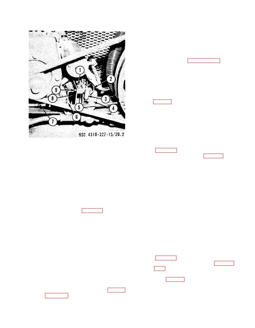
1 Screw
(1) R e m o v e the generator drive belt
2 Electrical lead
3 Capacitor
(2) Remove the screw (14, fig. 3-16) and
4 Voltage regulator
5 Shock mount
lockwasher that secure the adjusting
6 Screw
strap (10) to the generator (8).
7 Engine base
(3) Tag and disconnect electrical leads
8 Generator and regulator mounting bracket
(13) as necessary.
9 Screw
(4) Loosen screws (9) on mounting straps
(11) and remove the generator (8)
regulator mounting bracket, model BMW-452-ENG,
and mounting straps (11) from the
removal points.
mounting bracket (15).
c. Removal (Model BMW-452-ENG-1).
(5) Remove the nut (7) and lockwasher
(1) Tag and disconnect applicable elec-
from both ends of the stud and re-
trical leads (20, fig. 3-14).
move the mounting bracket and stud.
(2) Remove the screws (19) and lock-
(6) R e m o v e nut, screw (5) and lock-
washers that secure the voltage regu-
w a s h e r that secure the adjusting
lator (25) to the generator (22) and
strap (10) to the generator and re-
remove the voltage regulator.
gulator mounting bracket and remove
d. Cleaning and Inspection.
the adjusting strap.
(1) Clean the exterior of the voltage reg-
b. Removal (Model BMW-452-ENG-1).
ulator with a cloth dampened with an
(1) R e m o v e the generator drive belt
approved cleaning solvent and dry
thoroughly.
(2) Remove the generator regulator (para
(2) Inspect for loose or damaged termi-
nals, bent or cracked cover, and oth-
(3) Tag and disconnect the electrical lead
er damage.
(21, fig. 3-14) and the ground (23)
(3) Replace a damaged voltage regulator.
(4) Remove the nut, lockwasher, screw
e. Installation (Model BMW-452-ENG).
(17) and flat washer that secures the
(1) Position the voltage regulator (4, fig.
generator to the adjusting strap (29).

