
3-23.
Air
Compresor
Vibrates
Excessively
Section
VI.
RADIO
INTERFERENCE
SUPPRESSION
3-24. Definitions
a. Interference. The term "interference" as
used herein applies to electrical disturbances
in the radio frequency range which are gen-
erated by the rotary compressor and which may
interfere with the proper operation of radio
receivers or other electronic equipment, or en-
able the enemy to locate the equipment.
terference suppression" as used herein ap-
plies to the methods used to eliminate or ef-
fectively reduce radio interference generated
by the rotary compressor.
3-25. General Methods Used to Attain
Proper Suppression
Essentially, suppression, is attained by pro-
viding a low resistance path to ground stray
currents. Methods used include shielding the
ignition and high-frequency wire, grounding
the frame with bonding straps, and using ca-
pacitors and resistors.
a. Primary Suppression Components. The
primary suppression components are those
whose primary function is to suppress radio in-
terference. These components are described
and located in the engine technical manual, TM
5-2805-208-14.
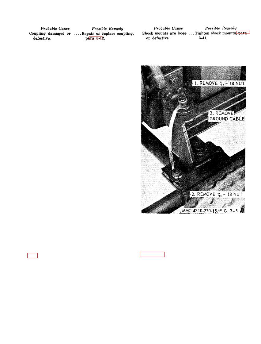
3-27. Replacement of Suppression
b. Secondary
Suppression Components.
Components
These components have radio interference sup-
a. Refer to engine TM 5-2805-208-14.
pression functions which are incidental and/or
b. Replace ground cable as illustrated in
secondary to their primary function, (ref fig.
3-28. Testing of Radio Interference Sup-
pression Components
Test the capacitors for leaks and shorts on a
capacitor tester; replace defective capacitors.
If test equipment is not available and inter-
ference is indicated, isolate cause by the trial-
and-error method of replacing each capacitor
in turn until the cause of interference is locat-
ed and eliminated.

