
Section VII. AIR INTAKE AND DISCHARGE SYSTEM
ever pressure in the air compressor rises
3-29. General
above 6.8 psi.
The air intake system of the rotary com-
pressor consists of a blower air filter mount-
3-30. Blower Air Filter
ed on the right side of the air blower. The air
discharge system is comprised of a manifold
a. Removal.
and air relief valve. Connected to the manifold
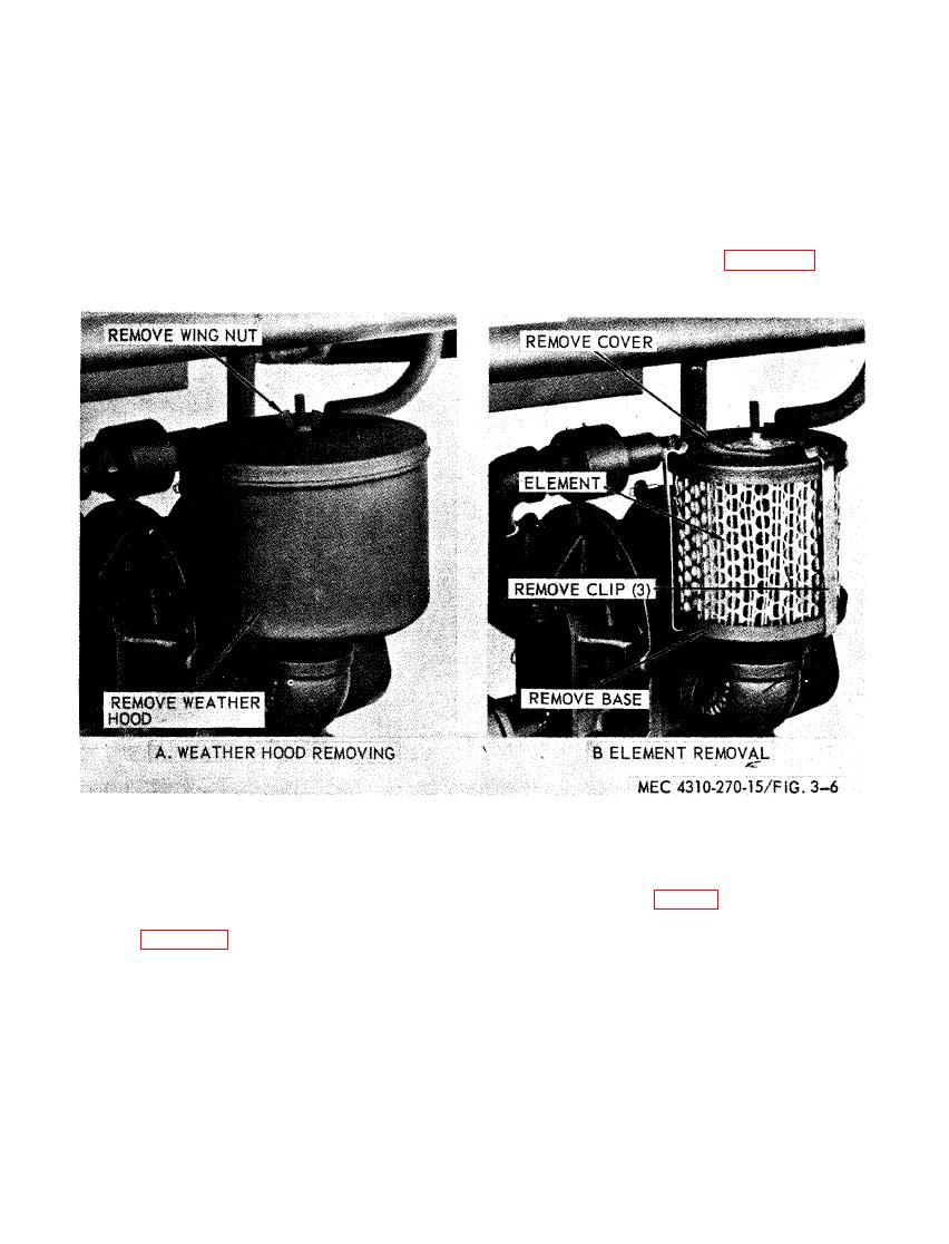
(1) Remove the weather hood and ele-
are two air hoses used for inflating. The air
ment as illustrated in figure 3-6.
relief valve is preset to discharge air when-
(2) If required, remove filter base.
b. Cleaning. Clean and inspect, replace ele-
a. Removal. Remove air relief valve from
ment as required.
90 degree elbow, (ref fig. 3-7).
c. Installation. Install the air filter as illus-
trated in figure 3-6.

