
b. Adjustment.
(1) To adjust air-relief valve, remove
90 degree elbow.
(2) Install a one inch tee with the use of
a close nipple.
(3) Install the air-relief valve at one port
and a pressure gauge at the other.
(4) Install both deadend fittings to the
manifold.
(5) Start Engine. The pressure gauge
should indicate 7.5 P.S.I. and the air-
relief valve should be fully opened.
(6) Remove the deadend fittings on the
manifold; the pressure gauge should
indicate 6.5 P.S.I. with no leakage
from the air-relief valve.
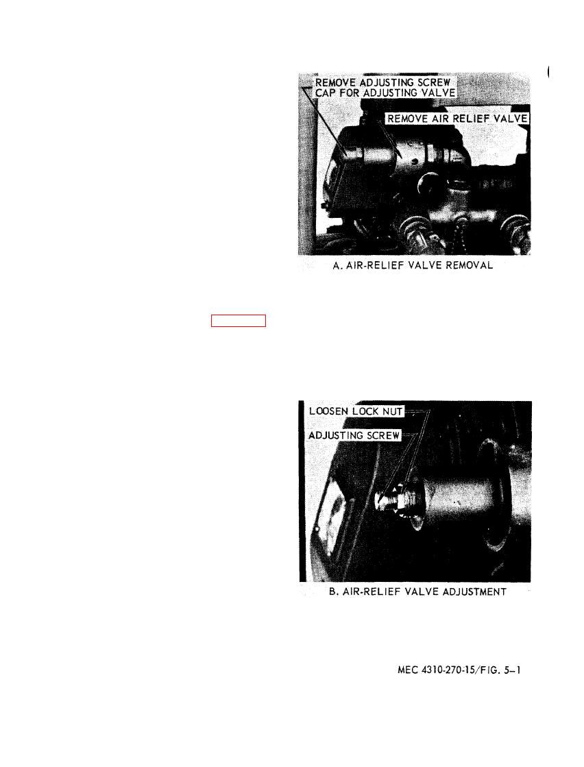
(7) To adjust the air-relief valve, remove
the hood and loosen the lock nut and
turn the adjusting screw counter-
clockwise until operational pressure
is 6.5 P.S.I. and the relief pressure
is 7.5 P.S.I. as shown by figure 5-1.
5-2

