
CHAPTER 6
COMPRESSOR REPAIR INSTRUCTIONS
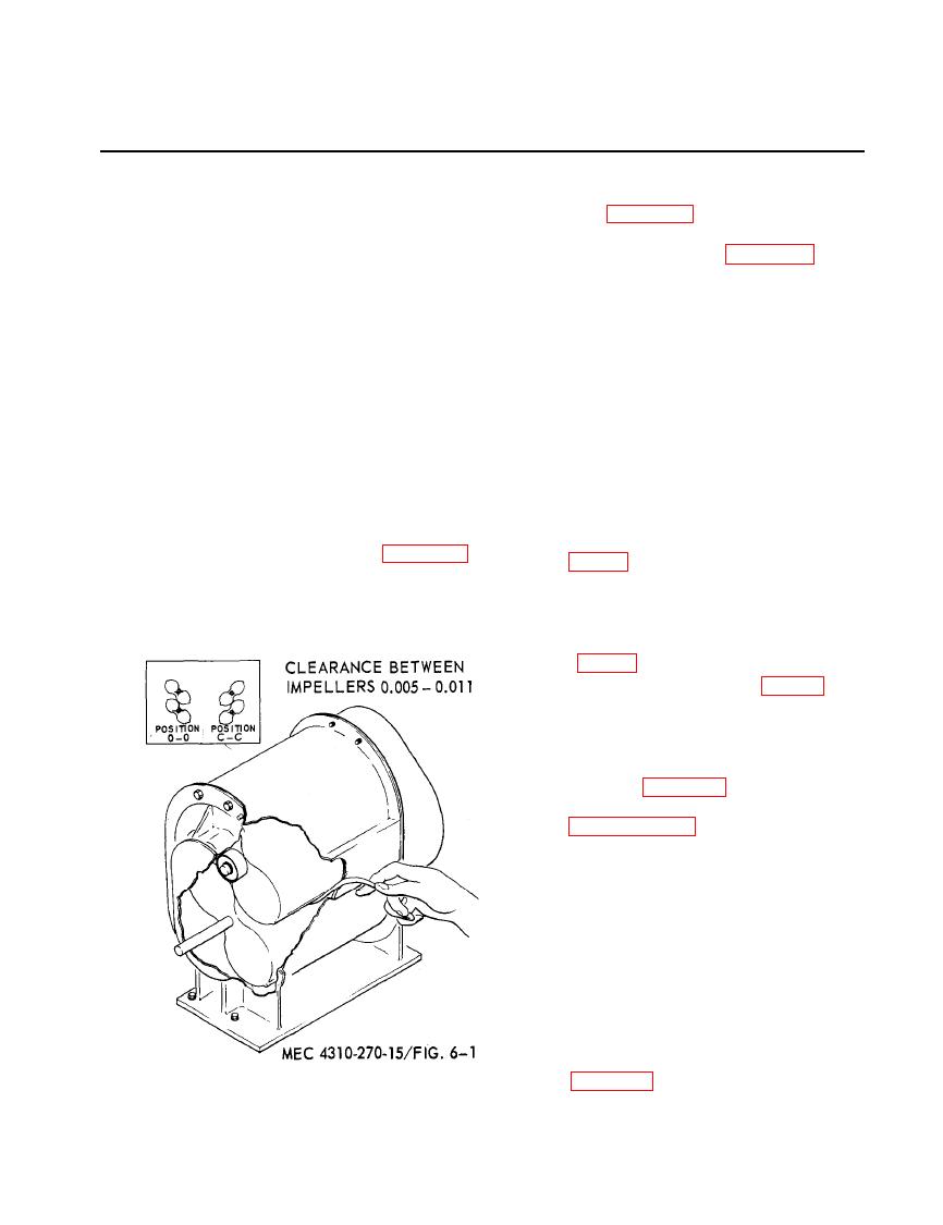
b. To Determine Total Clearance.
General
(1) Place the impellers in the 0-0 posi-
The air compressor has two figure eight im-
tion, figure 6-1.
pellers rotating in opposite directions. As each
(2) Measure the distance between 0-0
lobe of an impeller passes the blower inlet, it
with a feeler gauge, figure 6-1.
traps a quantity of air equal to exactly one-
(3) Rotate the impellers 90 degrees to
fourth the displacement of the compressor.
position c-c and measure distance be-
This entrapment occurs four times per revo-
tween c-c.
lution, moving the entrained air around the
(4) Add measurements 0-0 and c-c for
case to the blower outlet. Timing gears accu-
Desired clearance
total clearance.
rately position the impellers in relation to each
.005-.011.
other, maintaining the minute clearances so
c. To Determine Correct Clearance. Divide
vital to the high volumetric efficiency of the
the total clearance evenly between points 0-0
rotary positive blower.
and c-c.
Clearances
a. Impellers are held in time by taper pins
a. The clearances between impellers are
which secure the shaft and timing gears. To
measured at points 0-0 and c-c when the im-
re-time, it is necessary to remove only one ta-
pellers are in the position shown in figure 6-1.
per pin, (fig. 6-2).
The impellers are viewed from the drive end
(1) Insert a short length of pipe over the
of the blower; always face the drive shaft
shaft, clearing the taper pin, and
when determining clearances.
drive the timing gear further into the
shaft. This will loosen the taper pin,
(2) Remove the taper pin, (fig. 6-4).
(3) With a gear puller, pull the gear
away from the blower so that the
front face of the gear is 1/16 of an
inch past the front face of the mat-
ing gear, figure 6-5.
(4) Determine the correct clearance,
(5) Insert shim stock of proper thickness
between the impellers (because the
unit is out of time, it will probably be
necessary to wedge the shim stock
into position by rotating the impel-
lers).
(6) Place a short length against the un-
pinned gear and strike the pipe a
quick blow. This will drive the gear
further into the shaft, causing it to
turn relative to the shaft because of
the torque set up by the shim stock,

