
TM 5-4310-276-14
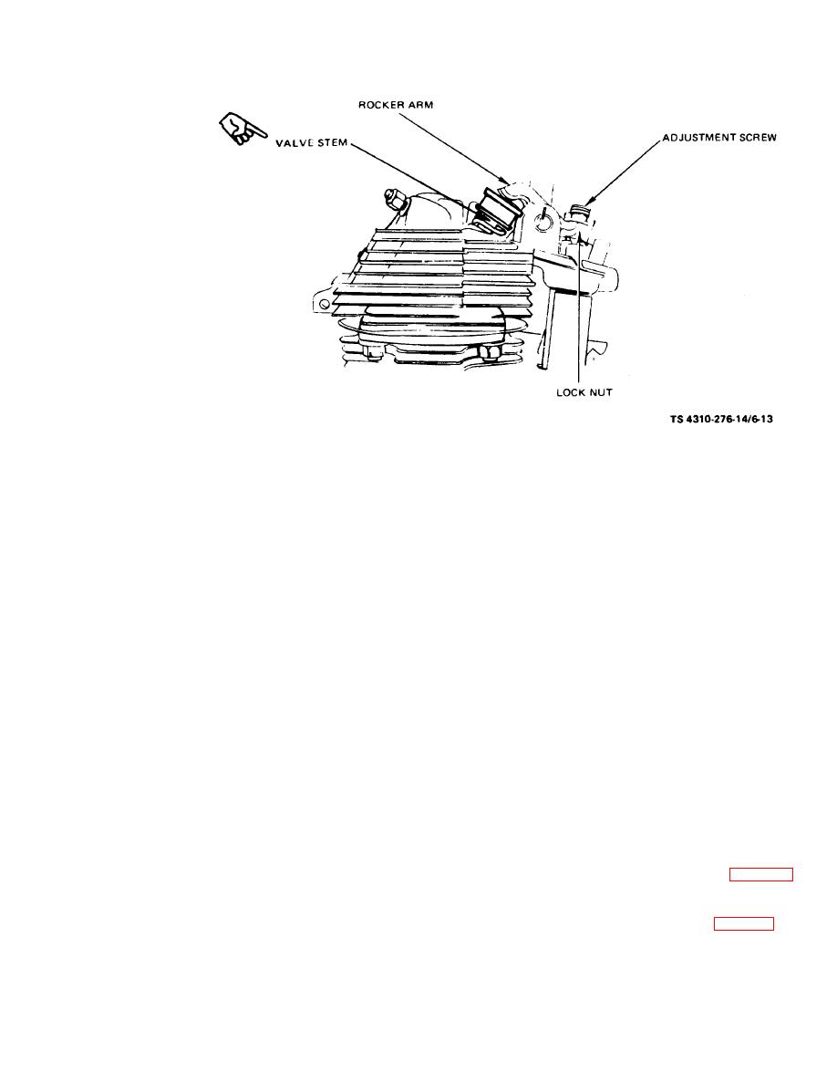
(2) Insert a feeler gage between the end of the
(4) Tighten locknut and remeasure clearance
valve stem and the face of the rocker arm. Continue
to be sure adjustment is correct.
to rotate the crankshaft and measure the clearance,
Correct clearance is 0.007 in. to 0.009 in. cold (0.017
NOTE
cm to 0.022 cm),
Adjust clearance on all models in the same manner.
(3) To adjust clearance, loosen the locknut
and turn the adjustment screw until measured
clearance is 0.007 in. to 0.009 in. cold (0,017 cm to
(6) Install new gasket with valve cover and
0.022 cm).
fasten with mounting screw.
(7) Install relief valve.
Section VI.
PISTON AND CONNECTING ROD ASSEMBLY
6-13. General
6 - 1 4 . Piston and Connecting Rod As-
sembly
Fitted into the bore of the cylinder is a movable
a. Removal.
piston that receives the energy or force of com-
(1) Remove the V-belt guard and the V-belts.
bustion and transmits the energy to the crankshaft
through the connecting rod. Piston rings are used
suitable container.
on pistons to maintain gastight seals between the
(3) Extract mounting bolts and remove en-
pistons and cylinders, to assist in cooling the piston,
gine, placing it on suitable work area.
and to control cylinder wall lubrication. The con-
(4) Remove the cylinder head assembly (para.
netting rod connects the piston with the crank-
6-11).
ha ft.
(6) Remove carbon deposit from top of cylin-
der.
Change 2

