
TM 5-4310-277-14
crimped. Check that the glass bowl on the fuel filter
tank is being filled. Always provide a metal-
is secure and not cracked or broken.
to-metal contact between the container and
tank to prevent a spark from being
g. Correct all deficiencies or report them to the
proper authority.
generated as gasoline flows over the
metallic serfaces.
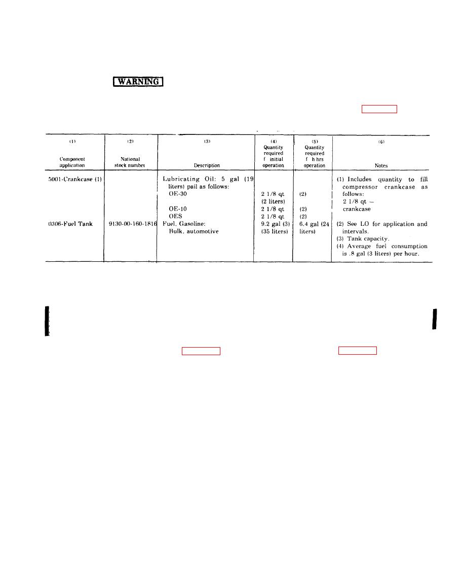
h. The maintenance and operating supplies
Do not fill the fuel tank while the engine is
running. Be sure there are no open flames
required for the initial eight hours of operation for
that may ignite the fuel vapors while the
the compressor are contained in table 4-1.
4-2. Installation
a. Installation of Separately Packed Com-
b. Installation or Setting Up Instructions.
ponents.
(1) General. Model BGR-5M-1 is primarily
designed for mobile field use when trailer mounted
and requires no special base. The Models HGR5-8M-
hose assembly, inflator gage (and globe valve with
1, and HGR5-8M-6 set directly on four feet welded
Models HGR5-8M-1 and HGR5-8M-6), packed sepa-
to the bottom of the air receiver and may be per-
rately.
manently installed if desired. If a permanent base is
(2) Install the air hose assembly, inflator
to be constructed, refer to figure 4-4.
gage, and globe valve as illustrated in figure 4-5.
Change 1

