
TM 5-4310-335-14
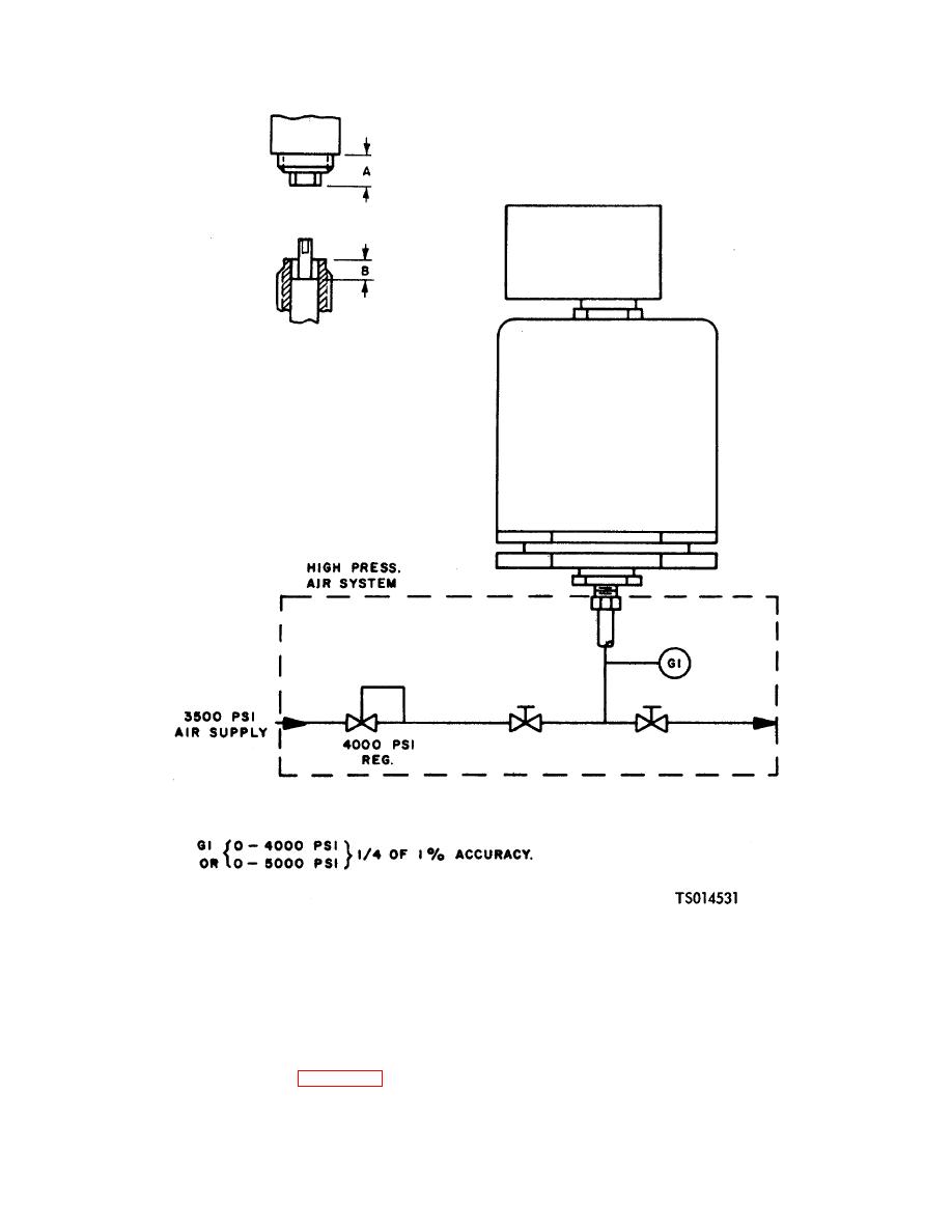
Figure 6-14. Unloader Valve Setting and Testing Setup.
a 0.157 inch (.3988 cm)-0.217 inch (,5512 cm) gap between the head of screw (17) and the actuator knob.
(p) Gradually increase the incoming pressure until control valve (15) actuates (lever in UP position).
Decrease pressure to 2775 psi (195.0825 kgs per sq cm). Slowly turn screw (17) into the plunger until the
valve reactuates (lever in DOWN position).
(q) Lockwire plug (2) and nut (1) to body (23).
(r) Lockwire jam nut (21) to body (23) and stop nut (20) to jam nut (21).
(s) Test the assembled unloader valve as follows:
1. Using the setup in figure 6-14, slowly apply pressure until valve actuates (clicks and
6-23

