
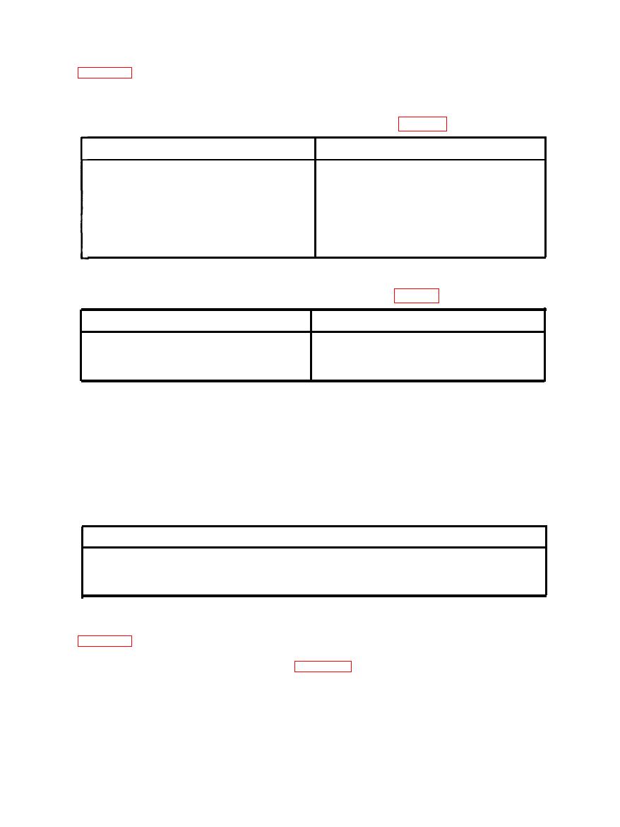
TABLE 3-1. OPERATING CONTROLS (REF FIG. 1-1. )
Action
Control
Motor Controller
Position as required
On-Off Snapswitch
Push to reset
Reset Pushbutton
Open to drain receiver
Receiver Drain Valve
TABLE 3-2. INDICATING DEVICES (REF FIG. 1-1. )
Normal Operating Indication
Device
Pressure Gauge
175-to 200-PSIG
Receiver
STARTING. Start the compressor by placing the motor controller snapswitch in the
ON position. The compressor will start and stop automatically in accordance with air
demand.
STOPPING. The unit is stopped by moving the motor controller snapswitch to the
OFF position.
TABLE 3-3. OPERATING LIMITS
PRESSURE LIMITS , PSIG
60
First Stage Safety Valve Setting
200
Second Stage Safety Valve Setting
OPERATOR'S MAINTENANCE. The maintenance procedures as recommended in
parts replacement functions that may be readily performed by the operator. More detailed
maintenance procedures are described in Section V - Maintenance and Repair. Where a
choice between a number of operational hours and a time exists, the choice shall be the one
that occurs first.

