
a. First dehydrator (nearest filter):
1. Press Iever on quick - disconnect ring and
lower polycarbonate shell from top casing
as shown in Fig. 6.
2. Pour out used desiccant. Open can of new
desiccant No. 85-059 - and pour contents
into shell of unit.
3. Fill to top. Shake or tap to settle desiccant,
then add or remove enough so that level is
1/8 inch below O-ring level on center tube.
Avoid pouring desiccant down center tube.
4. Replace shell assembly to top casing and
lock in place by rotating quick - disconnect
ring until lever snaps closed.
b. Second dehydrator (nearest regulator)
1. Press lever on quick - disconnect ring and
lower polycarbonate shell from top casing
as shown in Fig. 6.
2. Pour out used desiccant. Open can of new
desiccant No. 85-060 - and pour contents
into shell of unit.
3. Fill to top. Shake or tap to settle desiccant,
then add or remove enough so that level is
1/8 inch below O-ring level on center tube.
Avoid pouring desiccant down center tube.
4. Replace shell assembly to top casing and
lock in place by rotating quick - disconnect
ring until lever snaps closed.
E. EQUIPMENT CONVERSION
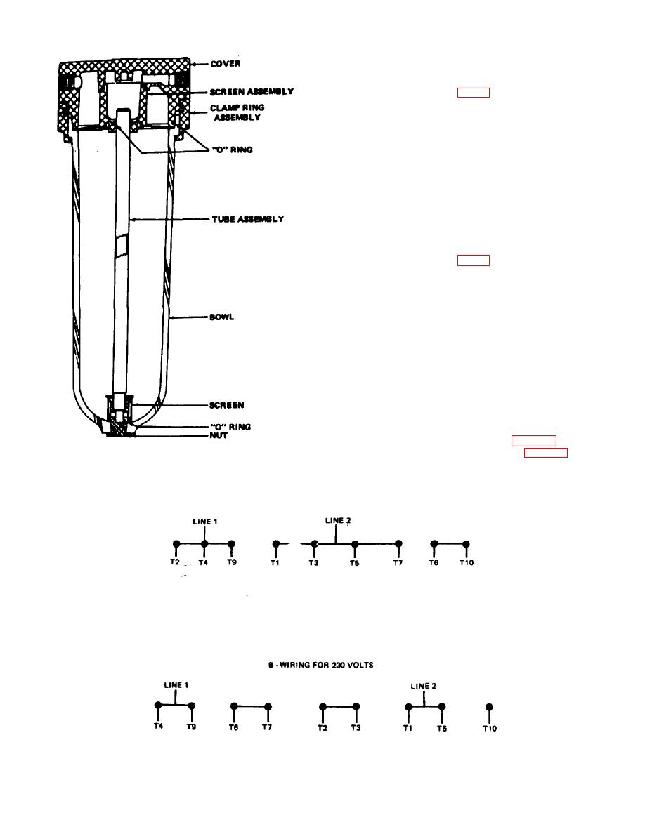
1. Electric Motor Wiring for 115 Volts
a. Remove junction box cover on motor.
b. Wiring should be as shown in figure 7A.
c. Install the relay heater (refer to figure 8) marked
Figure 6. Desiccant installation.
H-41. They relay heater (H-41) is factory installed.
A -WIRING FOR 115 VOLTS
Figure 7. Electric motor wiring.
5

