
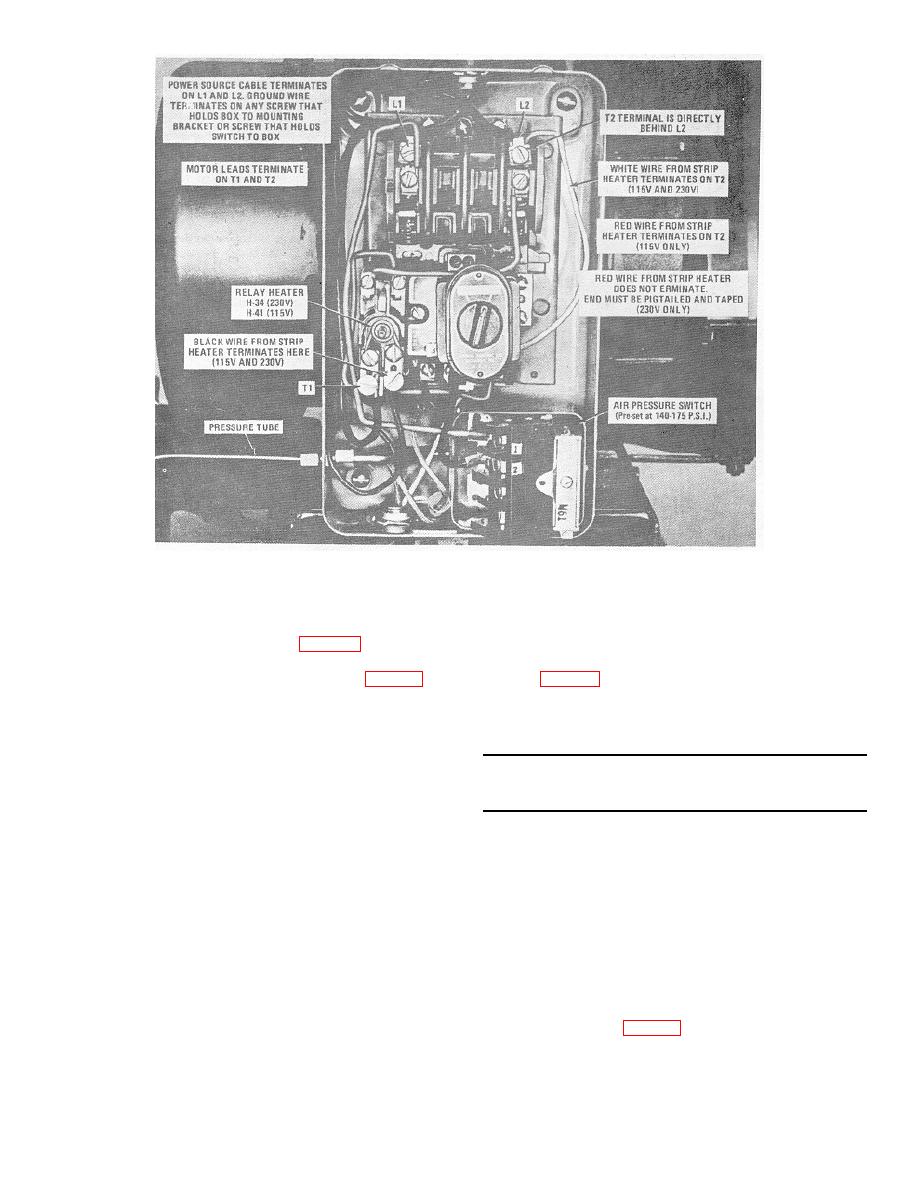
Figure 8. Magnetic Starter (shown with cover removed).
bolted or clamped to the water pipe or ground rod, and
2. Electric Motor Wiring for 230 Volts
the feet or motor platform of the air receiver tank of the
a. R(emov4 junction box cover on motor.
air compressor.
b. Wiring should be as shown in figure 7B.
3. Connecting the Incoming Power Source.
c. Remove relay heater marked H-41 and replace
a. Remove the cover from the magnetic starter
with relay heater marked H-34 (refer to figure 8).
b. Remove knockout plug from the starter box and
F. INSTALLATION OR SET-UP INSTRUCTIONS
insert the incoming power source wires through
1. Location and Leveling. Locate the air compressor as
the opening.
near to the electrical power source as possible. Avoid
muddy, sandy or dusty locations if possible. If it is
WARNING: Be sure the incoming power lines are
necessary to use the unit on soft ground, provide a
connected to a disconnect switch that is locked in the
suitable, level foundation of planking.
OFF position before handling the wires.
2. Grounding. The air compressor must be grounded
prior to operation. The ground lead-may be connected to
c. Insert the bare ends of the incoming power
an underground water system if the water system is
source wires in the L-1 power line connector and
constructed of metallic pipe. A ground may be fabricated
L-2 power line connector and tighten the terminal
from a metallic rod driven not less than 4 feet into the
screws.
ground.
The ground lead must be securely
d. Install cover on the magnetic starter.
SECTION III
CONTROLS AND INSTRUMENTS
A. GENERAL
B. GLOBE VALVE
This section describes, locates, illustrates and
The glove valve (figure 1) mounted on the end of the
furnishes the operator sufficient information pertaining to
air receiver tank is a manually operated valve that opens
the various controls and instruments/provided for the
the flow of compressed air-to the filter, dehydrator,
proper operation of the air compressor.
regulating valve and air hose.
6

