
TM 5-4310-349-14
1.
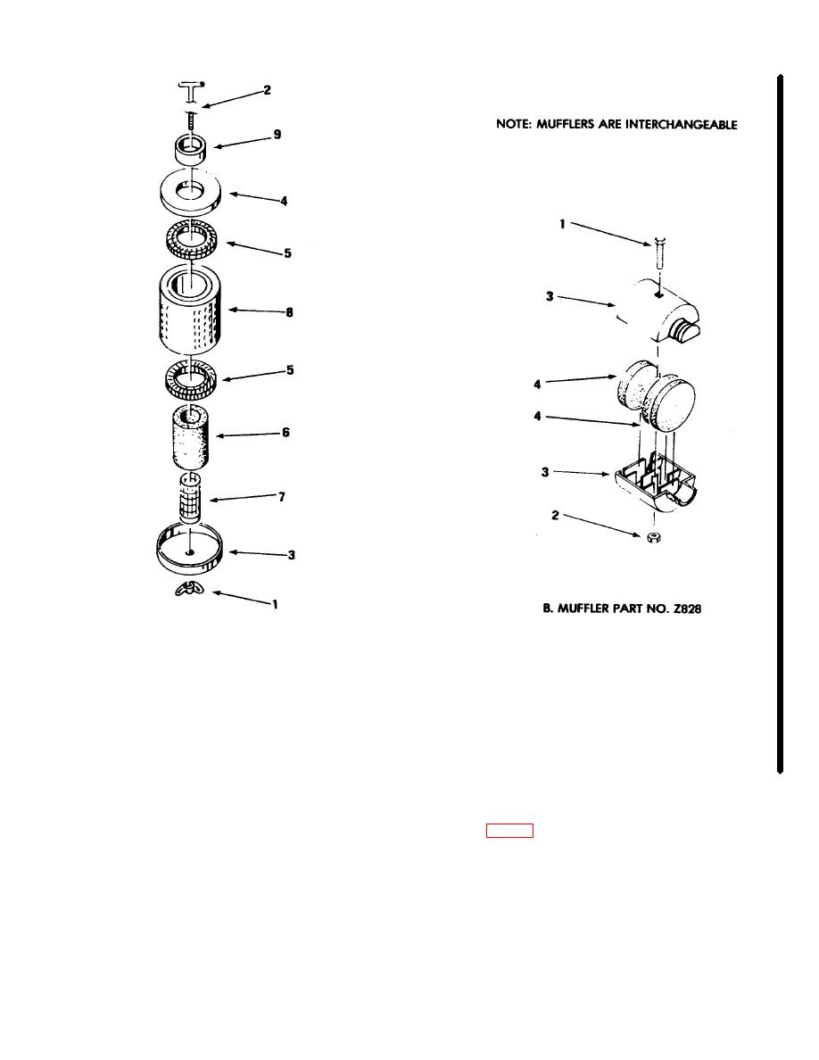
SCREW MACHINE
A.
MUFFLER PART NO. Z66A
2.
PLAIN
3.
INTAKE, AIR
1.
T-STUD
5.
SEPARATOR
4.
FILTER ELEMENT
2.
NUT, WING
6.
ELEMENT
3.
COVER, LOWER
7.
SCREEN
4.
COVER, UPPER
8.
PLATE
9.
FERRULE
ME 4310-133-3512-14/3-3
Figure 3-3. Air intake mufflers, exploded view
moisture (condensate) into the receiver.
Frequent
c.
Draining Condensate from Air Receiver.
inspection and service is necessary.
(1) TURN ON-OFF switch to OFF.
b. Inspection and Cleaning.
(2) Open draincock at bottom of the air
(1) Inspect the receiver for excessive
receiver (fig. 1-1) under the service line.
accumulation of dust, and leaking or spilled compressor
(3) When air has escaped, leave draincock
oil.
open for a few minutes for more of the condensate to
(2) Check air lines and the service line for
escape.
leaking joints or damaged lines. Tighten loose fittings,
(4) Close draincock.
replace a damaged line.
(5) Be sure that all cloths, tools, etc., have
(3) Use compressed air to blow dust off the
been removed from the air receiver, then move ON-
receiver and all components mounted thereon. Wipe off
OFF switch to ON.
all oil spots, then dry, to avoid further accumulations.
Change 2 (3-8 blank)/3-7

