
TM
5-4310-350-14
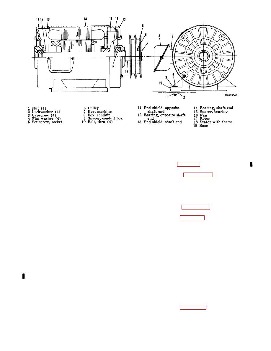
Figure 59. Electric motor assembly.
(2) Refer to figure 59 and disassemble
(3) Check on-off switch continuity and
stem action. Replace a defective on-off switch.
electric motor.
b. Cleaning, Inspection and Repair.
c. Reassembly and Installation.
(1) Clean all parts except rotor, bearings
(1) Refer to figure 5-11 or 5-11.1 and reas-
and stator in an approved cleaning solvent and
semble starter.
wipe dry with a lint free cloth.
(2) Refer to figure 5-10 and install the
(2) Use compressed air to clean dust and
magnetic starter in reverse order of the removal
dirt off rotor, bearings, and stator, then wipe with
procedure.
a cloth dampened in an approved cleaning solvent.
(3) Inspect bearings and rotor shaft for,
5 - 9 . Pressure Switch
excessive wear, and rough or scored surfaces.
a. Removal and Disassembly.
Replace defective bearings. Replace a defective
(1) Refer to figure 5-12 and remove the
rotor shaft.
pressure switch as shown.
c. Reassembly and Installation.
(2) Refer to figure 5-8 and disassemble the
(1) Refer to figure 5-9 reversing the pro-
pressure switch as shown.
cedures and reassemble the electric motor as
b. Cleaning, Inspection and Repair.
shown.
(1) Use compressed air and remove all dust
(2) Refer to paragraph 4-11 and install the
and dirt from pressure switch components, then
electric motor.
wipe with a cloth dampened in an approved
cleaning solvent.
5-8. Magnetic Starter
(2) Inspect the contact board contacts for
a. Removal and Disassembly.
pitting or burring.
(1) Refer to figure 5-10 and remove the
(3) Inspect diaphragm for cracks or breaks
magnetic starter as shown.
and general condition.
(2) Refer to figure 5-11 or 5-11.1 and disas-
(4) Inspect all threaded parts for damaged
semble starter as shown.
or defective threads.
b. Cleaning, Inspection and Repair.
(5) Repair or replace damaged or defective
(1) Use compressed air and remove all dust
parts as necessary.
or dirt from magnetic starter components.
c. Reassembly and lnstallation.
(2) Check continuity of heater coil, operat-
(1) Refer to figure 5-13 and reassemble the
ing coil, relay overload, contact carrier and inter-
pressure switch.
lock assembly, Replace defective parts.
5-16

