
TM 5-4310-352-14
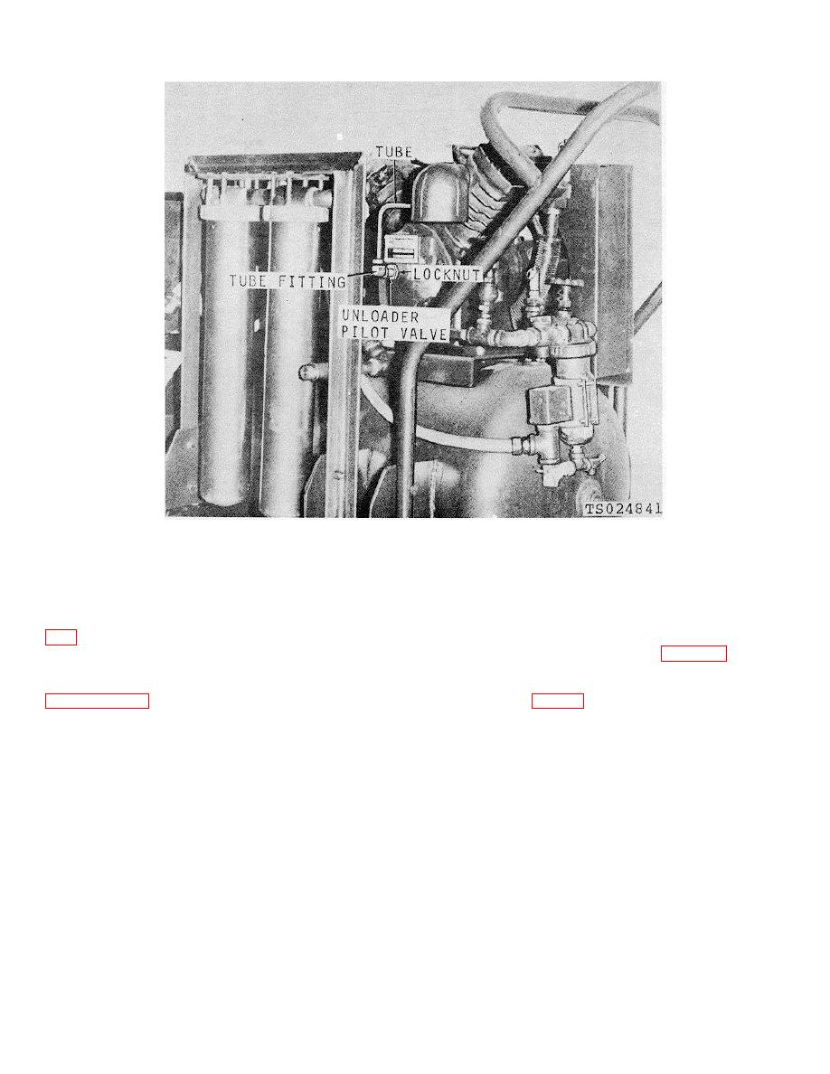
Figure 4-2. Pilot valve replacement.
(2) Remove tube fitting from pilot valve.
4-13. Crankshaft
(3) Loosen locknut securing pilot valve and
remove pilot valve from frame cover.
sionally diagnosed as a trouble area. When this occurs, it
b. Installation. Adjusting of the pilot valve is per-
must be inspected before further damage may occur.
formed during installation, therefore, refer to paragraph
b. Crankshaft Inspection.
(1) Stop the compressor.
(2) Remove the pilot valve (para 3-12).
(3) Drain oil from frame (L05-4310352-12).
4-12. Inlet Filter
(4) Remove cover from frame by removing the
a. Removal. Unscrew the inlet filter assembly (fig.
six capscrews (9, fig. 4-3.)
tive inlet filter.
b. Installation. Position the inlet filter assembly on
the close nipple and turn clockwise to tighten.
4-5


