
TM 5-4310-354-14
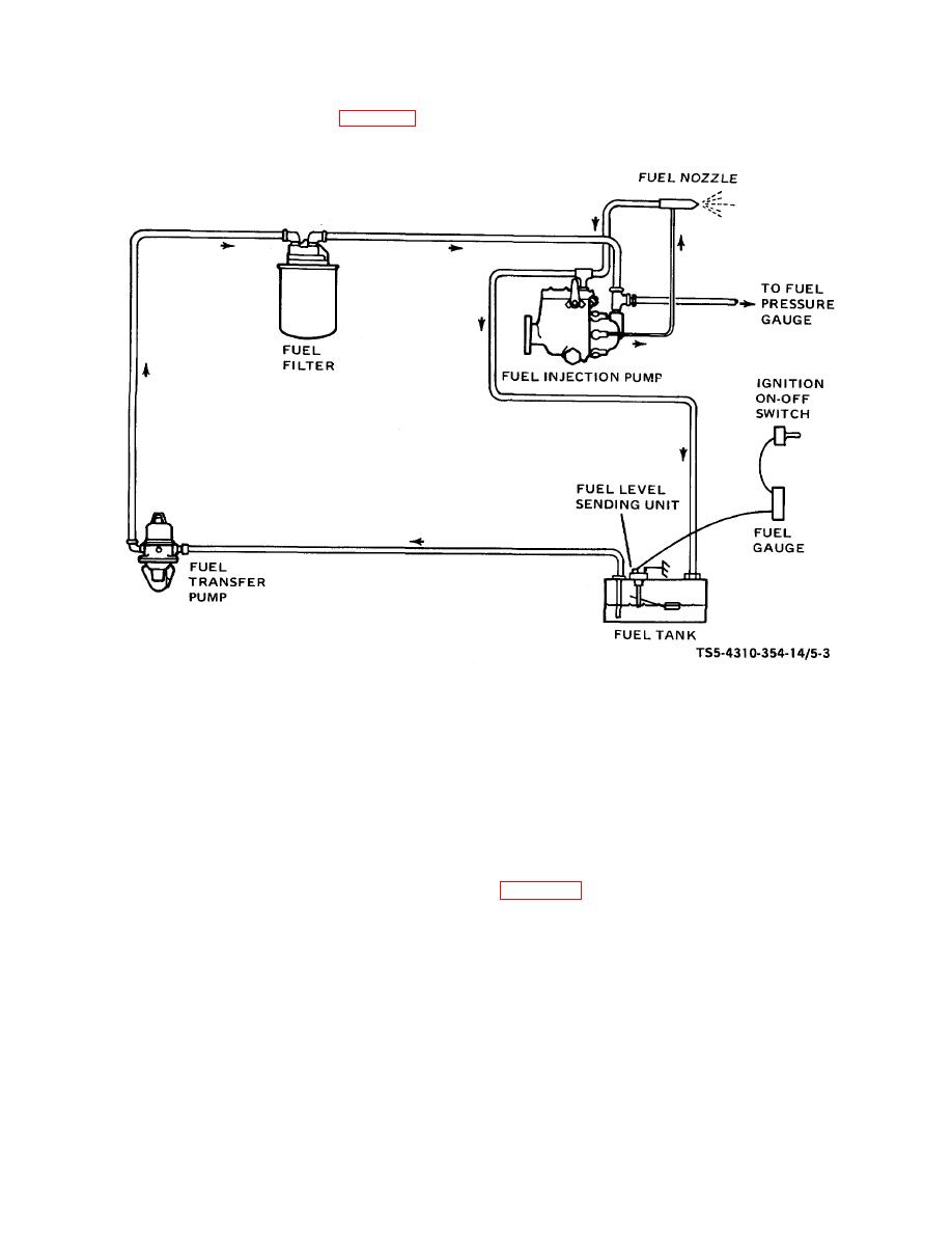
schematic diagram of the unit fuel system.
TS5-4310-354-14/5-3
Figure 5-3. Fuel system schematic diagram.
f. General Cleaning of Parts. In general, clean all
WARNING
metallic parts using cleaning solvent, Federal
Specification P-D-680, Type II. Clean non-metallic parts
Dry cleaning solvent, P-D-680, used
with a clean, lint-free cloth dampened with this same
to
clean
parts
is
potentially
solvent. Dry all parts thoroughly. Any cleaning that
dangerous
to
personnel
and
differs from this general method will be found in
property.
Avoid repeated and
instructions for that specific item.
prolonged skin contact. Do not use
near open flame or excessive heat.
g. Repair and Replacement Standards. Refer to
Flash point of solvent is 100 F-130 F
(38 C-59 C).
recommended by the manufacturer for engine and
compressor components.
5-13

