TM 5-4310-354-14
1.
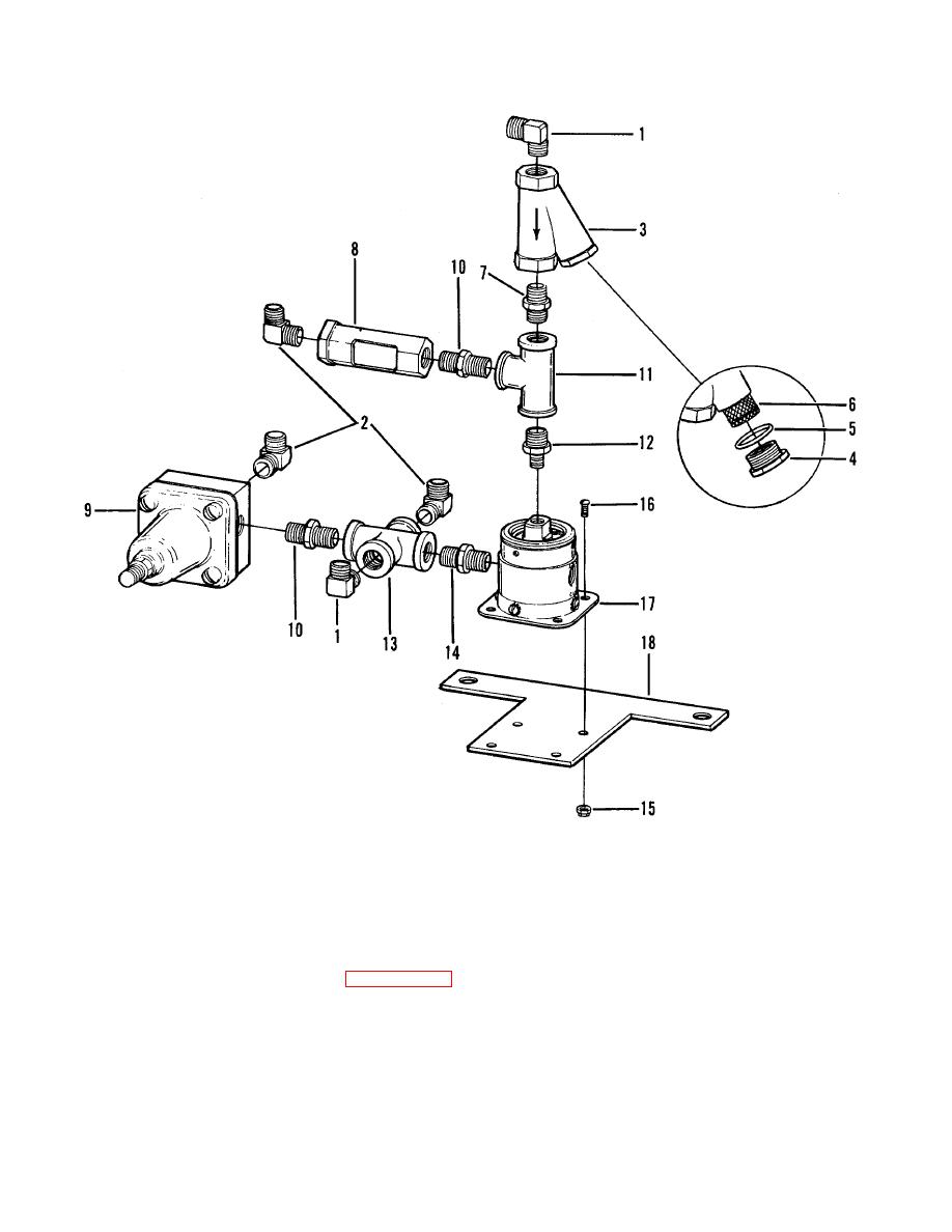
Elbow (2)
10.
Hex nipple (2)
2.
Elbow (3)
11.
Pipe tee
3.
Line strainer
12.
Hex nipple
4.
Strainer cap
13.
Pipe cross
5.
O-ring
14.
Hex nipple
6.
Screen element
15.
Lock nut (4)
7.
Orifice, "Y"
16.
Screw (4)
8.
Sight gauge
17.
Blowdown valve assy
9.
Air pressure regulator
18.
Mounting bracket
TS5-4310-354-14/6-4
Figure 6-4. Blowdown valve assembly, disassembly and reassembly.
(1) Remove the two elbows (1), three elbows
(3) Remove pipe tee (11), hex nipple (12),
(2), and line strainer (3). Remove strainer
pipe cross (13), and hex nipple (14).
cap (4), o-ring (5), and screen element (6).
(4) Remove four lock nuts (15), four screws
(2) Remove orifice (7) and sight gauge (8).
(16), and separate blowdown valve
Remove air pressure regulator (9) and two
assembly (17) from mounting bracket (18).
hex nipples (10). Refer to paragraph 6-7
for air pressure regulator (9) details.
6-7


