
TM 5-4310-354-14
TS5-4310-354-14/7-1
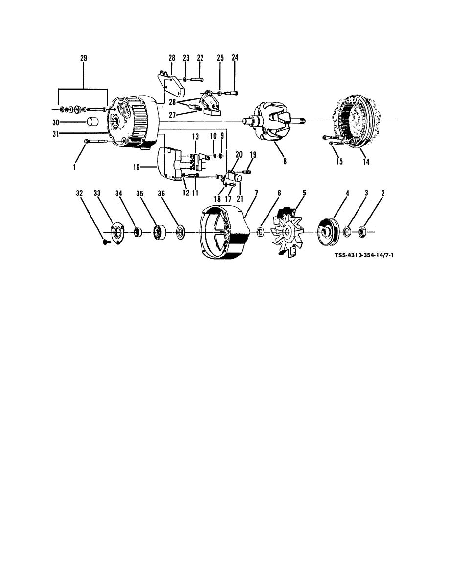
1.
Through bolts (4)
13.
Diode trio
2.
Shaft nut
14.
Stator assembly
25.
Insulator
3.
Lock washer
15.
Stator lead clip (2)
26.
Brush and holder
4.
Pulley
16.
Rectifier bridge
27.
Brush spring
5.
Fan
17.
Screw
28.
Regulator
6.
Outside collar
18.
Lock washer
29.
Terminal package
7.
Drive end frame
19.
Screw and lock washer
30.
Bearing
8.
Rotor assembly
20.
Capacitor bracket
31.
Slip ring end frame
9.
Nut (3)
21.
Capacitor
32.
Screw (3)
10.
Lock washer (3)
22.
Screw (2)
33.
Retainer
11.
Screw
23.
Lock washer (2)
34.
Inside collar
12.
Lock washer
24.
Insulated screw
35.
Bearing
36.
Grease slinger
Figure 7-1. Alternator assembly, disassembly and reassembly.
(1) Scribe a mark for reassembly location on
(2) After separating end frames (31, 7), place
slip ring end frame (31) and drive end
a piece of tape over slip ring end frame
frame (7). Remove the four through bolts
bearing and rotor shaft on the slip ring end
(1) and using a screwdriver at the stator
of rotor assembly (8) to prevent shaft
slots separate the drive end frame (7) and
damage and dirt from entering bearing.
rotor assembly (8) from the stator
assembly (14).
CAUTION
Do not overtighten vise when holding
CAUTION
rotor assembly (8) for shaft nut (2)
Do not use a tape that will leave a
removal.
gummy deposit on bearing or rotor
shaft.
7-2

