
TM 5-4310-354-14
(1) Reassemble field coil assembly (40) into
pliers as shown in figure 7-13. Remove
starter frame (41), assemble grommet
the washer. lubricate the armature (19)
(39), four pole shoes (38), and attach with
shaft and spline with Delco-Remy
four pole shoe screws (37).
Lubricant No. 1960954, or equivalent.
(2) If the two support packages (36) were
(6) Reassemble armature (19) into starter
disassembled, reassemble two ground
frame (41) and place washer (18) on
leads (35), brush holder supports (34),
armature shaft.
screws (33), lock washers (32), and nuts
(31).
(7) If disassembled, reassemble dowel pin
(17), bushing (12) into housing (11) and
(3) Reassemble two brush springs (30), two
bushing (10) into end frame (9). Lubricate
insulating brush holders (29), two ground
bushings (12, 10) with Delco-Remy
brush holders (28), attach with brush
Lubricant No. 1960954, or equivalent.
holder pins (27).
Reassemble four
brushes (26), two insulating brush screws
(8) Reassemble shift lever (16), lever stud
(25), and two ground brush screws (24).
(15), lock washer (14), and nut (13) in
drive housing (11).
Assemble drive
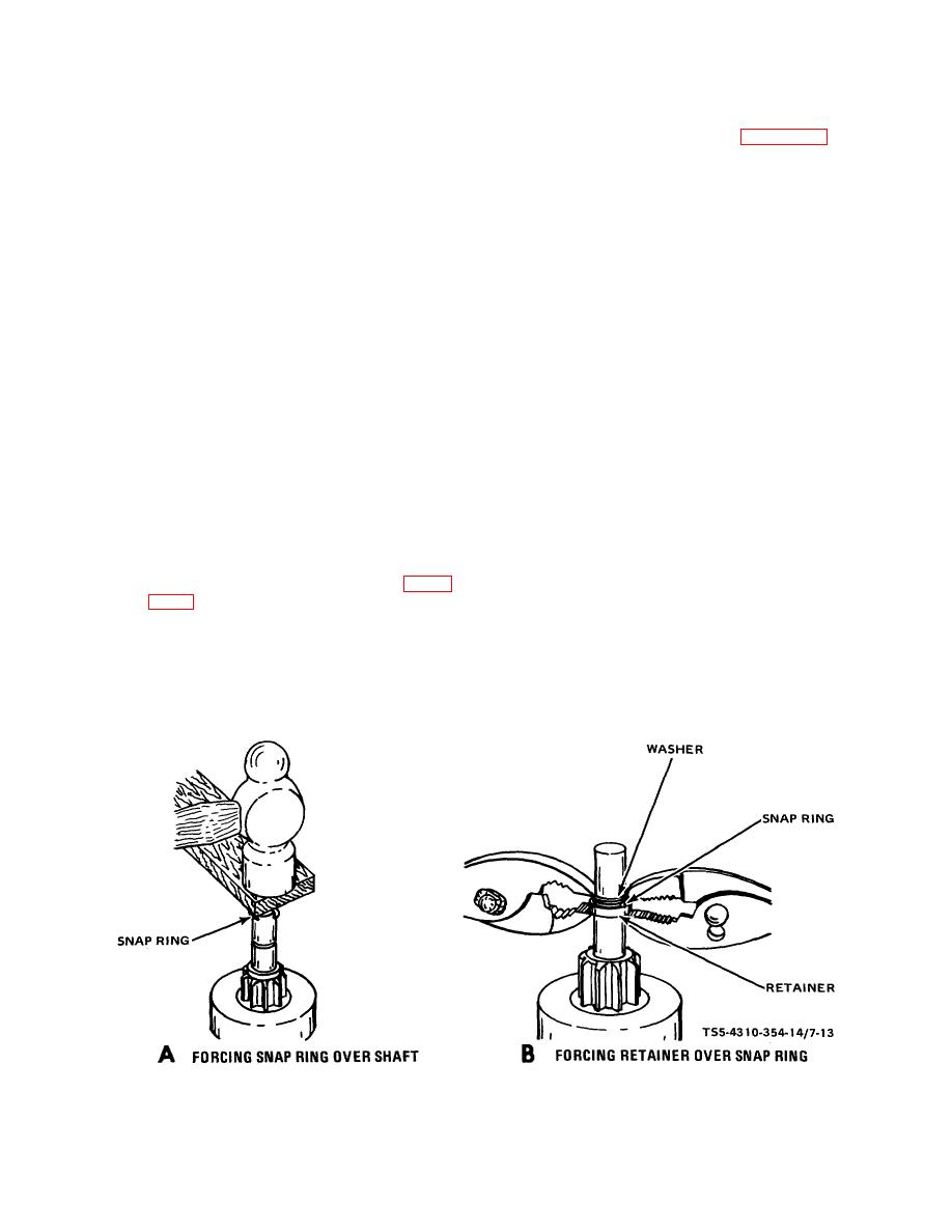
(4) Place clutch and drive assembly (23) on
housing (11) to starter frame (41) with shift
armature (19) shaft, place retainer (22) on
lever (16) engaged with groove of clutch
shaft with cupped surface facing the
and drive assembly (23).
retaining ring groove on shaft. Place the
retaining ring (21) on the end of the
(9) Reassemble commutator end frame (9) on
armature shaft. Using a piece of wood,
starter frame and install two through bolts
force the retaining ring over the shaft with
(8).
a light hammer blow as shown in figure
(10) Reassemble plunger (7) to shift lever (16)
the groove.
with lever pin (6). Assemble spring (5)
and solenoid switch (4) over plunger and
(5) Force the retainer over the retaining ring
attach solenoid switch (4) flange to drive
by placing a suitable washer over the
housing
shaft and squeeze retainer and washer
together with
TS5-4310-354-14/7-13
Figure 7-13. Installing clutch and drive assembly retainer and snap ring.
7-13

