
TM 5-4310-354-14
(11) with two lock washers (3) and screws
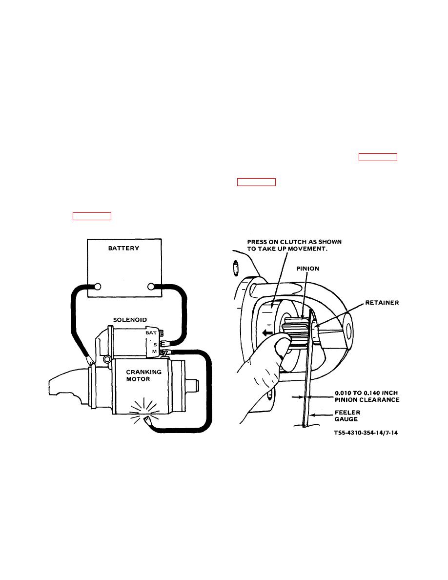
(c) MOMENTARILY flash a jumper lead from
(2). Reassemble screw and lock washer
the solenoid motor terminal to the solenoid
(1). Apply a suitable sealing compound
frame.
This will shift the pinion into
between solenoid, field frame, flange, and
cranking position and it will remain so until
junction.
the battery is disconnected.
(11) The pinion clearance cannot be adjusted but
(d) Push the pinion back towards the
should be checked after reassembly to ensure
commutator end to eliminate slack
proper clearance. Improper clearance is an
movement.
indication of worn parts. Check the clearance as
follows:
(e) Check the distance between pinion and
pinion stop as shown in figure 7-14.
(a) Disconnect the motor field coil connector
from the solenoid motor terminal and
g. Installation. Install the starting motor assembly
INSULATE IT CAREFULLY.
(b) Connect a 12-volt battery from solenoid
switch terminal to the solenoid frame
TS5-4310-354-14/7-14
A CIRUIT FOR CHECKING PINION CLEARANCE
B CHECKING PINION CLEARANCE
Figure 7-14. Checking pinion clearance.
7-14

