• Home
  • Download PDF
  • Order CD-ROM
  • Order in Print
Figure 7-15. Fuel injection pump, removal and installation (Sheet 2 of 3).
Figure 7-16. Fuel injection pump, disassembly and reassembly.

TM-5-4310-354-14 Compressor Rotary; Air Skid Mounted; Diesel Engine 125 CFM 100 PSIG (Davey Model 6M125) Manual
Page Navigation
  206    207    208    209    210  211  212    213    214    215    216  
TM 5-4310-354-14
TS5-4310-354-14/7-15 (3)
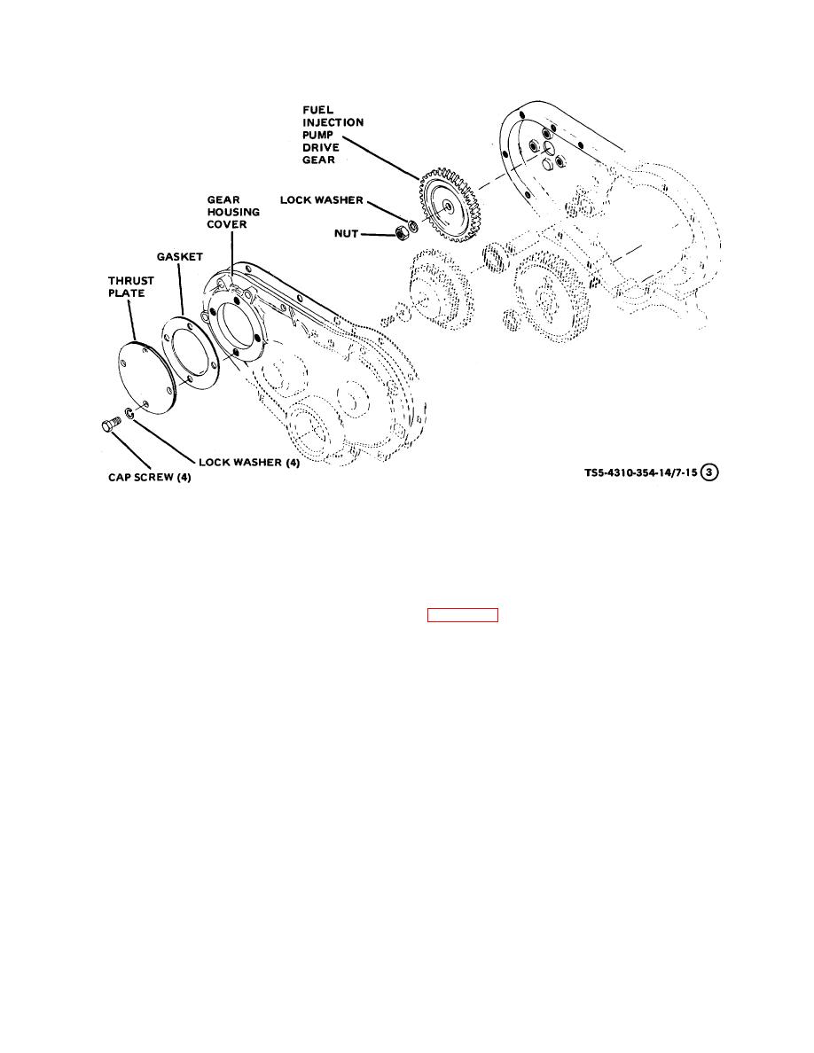
D INJECTION PUMP DRIVE GEAR
Figure 7-15. Fuel injection pump, removal and Installation (Sheet 3 of 3).
(8) Remove nuts, lock washers , and flat washers
b.
Disassembly.
Disassemble the fuel
that secure fuel injection pump to gear housing
injection pump in the numerical sequence shown in
studs. Remove the fuel injection pump.
figure 7-16 and detailed instructions as follows:
NOTE
If  fuel  injection  pump  is  to  be
transported  to  another  area,  or
stored, secure the throttle lever in full
open position after removal from
engine.
This  will  prevent  the
governor weights from dislodging
inside of the pump housing.
7-18


Western Governors University

Privacy Statement
Press Release
Contact

© Copyright Integrated Publishing, Inc.. All Rights Reserved. Design by Strategico.