
TM 5-4310-362-14
CHAPTER 2
OPERATING INSTRUCTIONS
Section I. DESCRIPTION AND USE OF OPERATORS
CONTROLS AND INDICATORS
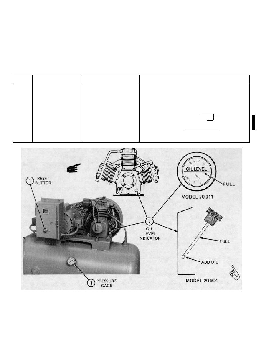
2-1. OPERATOR'S CONTROLS AND INDICATORS
KEY
NAME
LOCATION
FUNCTION
Main power switch
Main switch box
Turn electric power to the compressor set on and off
1
RESET button
Starter enclosure
Push to reset after overload condition has tripped
the protective relay
2
Oil level indicator
Shows oil level in crankcase.
Model 20-904
LOW mark - add oil Model 20-904
HIGH mark - oil level ok 24
FULL- indicating line
Model 20-911
3
Pressure gage
Air tank
Shows air pressure in tank
Change 1 2-1

