
TM 5-4310-362-14
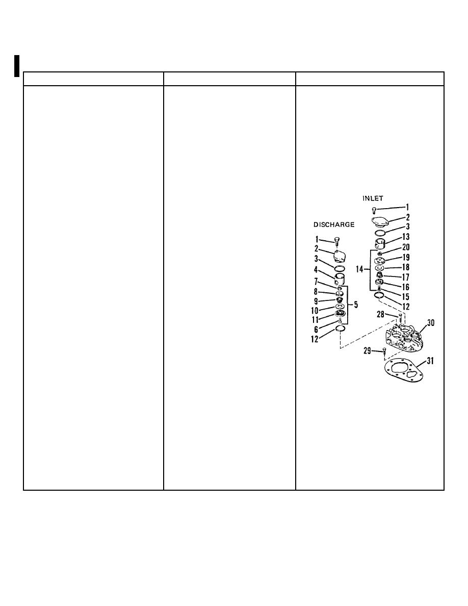
CYLINDER HEAD AND VALVES MODEL 20-904
LOCATION/ITEM
ACTION
REMARKS
8-11.
DISASSEMBLY
1.
Cylinder head screws (28
Remove
& 29)
2.
Cylinder head (30)
Remove
3.
Gasket (31)
Discard
Used gaskets will not seal and must be
discarded.
LOW PRESSURE
4.
Hold-down cover
Remove
screws (1)
5.
Holddown covers (2)
Remove
6.
O-ring (3)
Remove
7.
Valve cages (4 and 13)
Lift out of cylinder head.
8.
Low pressure valve as-
a. Lift out of cylinder head.
If necessary, tap valve assembly with a
semblies (5 and 14)
b. Clamp in soft jaw vise.
piece of wood to work it loose from the
c. Remove screws (6 and 15).
cylinder head.
NOTE
Do not mix up low pressure
inlet and discharge valve
parts. They are not inter-
changeable.
8-12 Change 1

