
TM 5-4310-368-14
(3)
Install and secure setscrew (29) and washer (30). (Figure 6-35)
(4)
Position gasket (17) and clutch housing (29) over four studs in engine. Secure with four nuts (21) and
washers. (Figure 6-34)
(5)
Insert clutch yoke (28) into inspection opening. Position ends of clutch yoke (28) over lugs on release
collar (3). (Figure 6-35)
(6)
Install yoke shaft (3) into clutch housing (29) and through yoke (28).
(7)
Align holes in yoke (28) with holes in yoke shaft (3). Secure with two roll pins (27).
(8)
Install clutch operating lever (1) over end of yoke shaft (3). Secure with pinch bolt (2).
(9)
Adjust clutch. Secure with adjustment lock (22), bolt (23) and washer (24). (Figure 6-35).
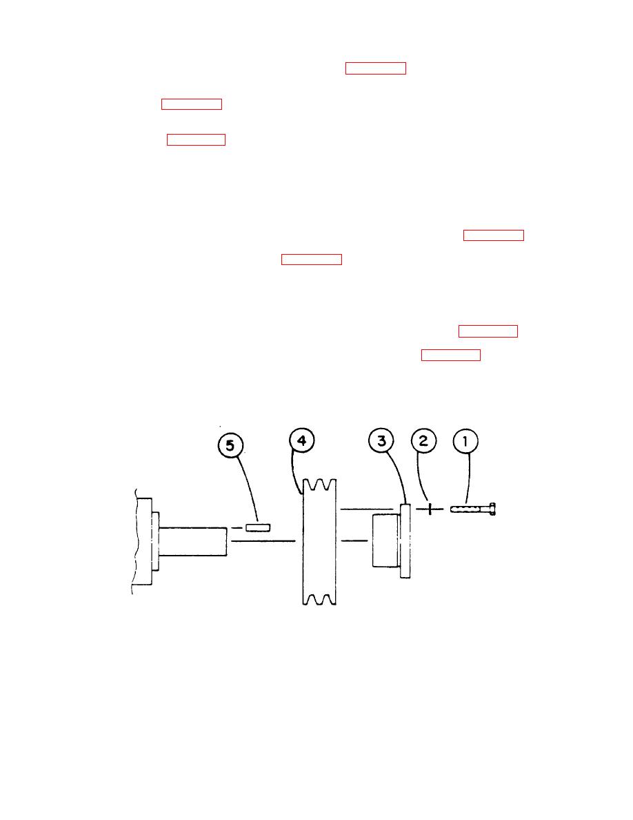
(10) Slide drive sheave onto PTO shaft. (Figure 6-36)
NOTE
Large diameter of tapered bore must be away from clutch housing (29).
(11) Install shaft key into keyway in PTO shaft. Slide bushing onto PTO shaft. (Figure 6-36)
(12) Install and secure three bolts and lock washers into drive sheave. (Figure 6-36)
(13) Fill with oil. Install and secure inspection cover, gasket, bolts and washers.
Figure 6-36. PTO Shaft
6-31

