
TM 5-4310-370-14
TM5-4310-370-14/5-7
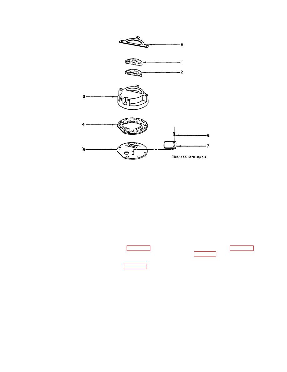
1.
Filter
5.
Valve Plate
2.
Filter Silencer
6.
Rolling Screw
3.
Reed Valve Head
7.
Reeed Valve
4.
Valve Plate Gasket
8.
Low Pressure Retainer
FIGURE 5-7. LOW PRESSURE HEAD ASSEMBLY
5-4. CYLINDERS, PISTONS ASSEMBLIES, AND CONNECTING ROD ASSEMBLY DISASSEMBLY.
a. Cylinder
(1) High Pressure Cylinder Removal
(a) Remove high pressure cylinder (figure 5-8, item 5) turning four hex cap screws (figure 5-8, item 2)
counter clockwise and then lifting off the cylinder from crankcase (figure 5-8, item 3).
(b) Remove cylinder flange gasket (figure 5-8, item 4).
(2) Low Pressure Cylinder Removal
5-19

