
TM 5-4310-371-14
TM 5-4310-371-14/5-11
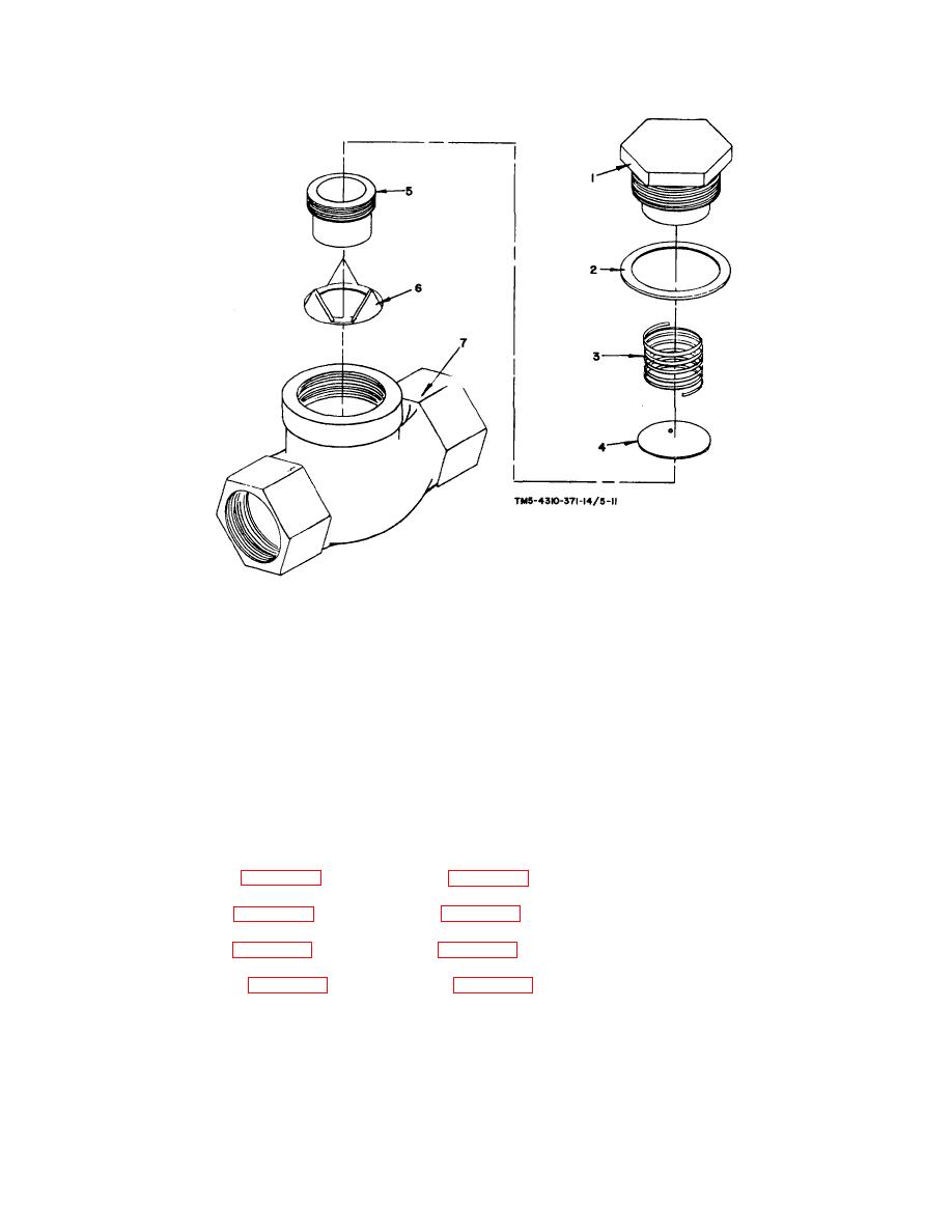
1.
Check valve cap
5. Check valve seat
2.
Check valve gasket
6. Check valve guide
3.
Check valve spring
7. Check valve body
4.
Check valve disc
FIGURE 5-11. CHECK VALVE REPAIR
(2) Inspect all parts for cracks, breaks, fissures, scores, distortions or any other damage.
(3) Replace check valve if any parts are found to be unserviceable.
d. Reassembly
(1) Install guide (figure 5-11, item 6) into body (figure 5-11, item 7).
(2) Install seat (figure 5-11, item 5) into body (figure 5-11, item 7).
(3) Install disc (figure 5-11, item 4) into body (figure 5-11, item 7).
(4) Install spring (figure 5-11, item 3) into body (figure 5-11, item 7).
5-36

