TM 5-4310-372-14
D. COMPRESSOR DRIVE AND BELT GUARD (4): Two V-belts transmit
power from the engine (1) to the compressor (3).
E. AIR RECEIVER (TANK) ASSEMBLY (5):
Stores the compressed
air produced by the compressor (3) for future use and /or
i n s t a n t
a v a i l a b i l i t y .
It is equipped with a gauge to
measure air pressure.
F. AIR DISCHARGE SYSTEM (6):
Controls the discharge of air
from the air receiver (5).
A 50 ft air hose is equipped
with an inflator gauge which is used to inflate tires and
to read tire pressure.
G. CAPACITY CONTROL SYSTEM (7):
Regulates the operation of
the compressor (3), and engine (l).
Prevents excessive
pressurization of the air receiver tank (5).
H. FUEL SYSTEM (8):
Stores gasoline for’ use by the engine
( l ) .
It is equipped with’ a fill cap and a strainer to
keep solid particles out of the fuel tank.
A level gauge
indicates the amount of fuel in the tank.
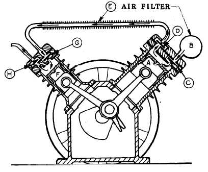
1-13. AIR COMPRESSOR OPERATION.
The picture below shows the
general operation of the air compressor.
The air. compressor has
two cylinders;
air from the low pressure cylinder feeds into an
intercooler and then into the high pressure cylinder.
1-7