
TM 5-4310-373-14
This task covers:
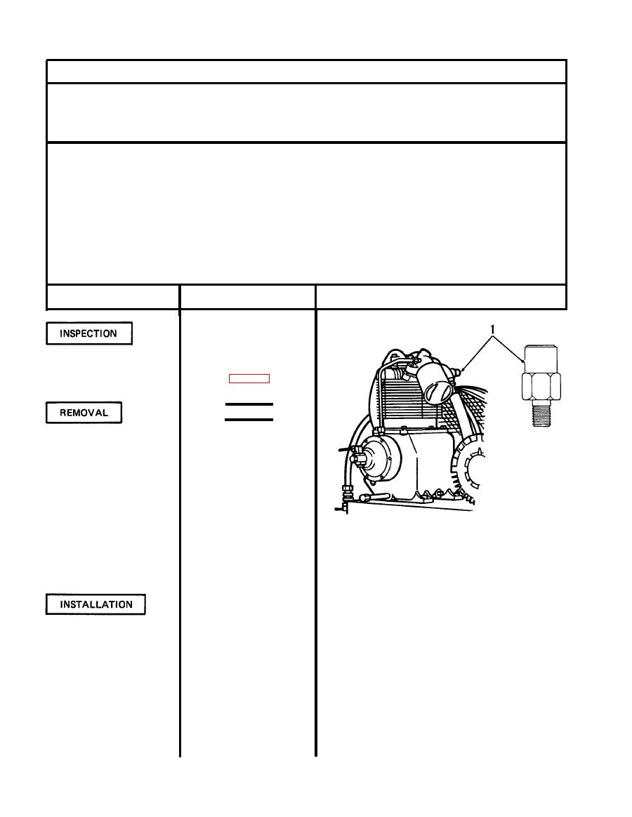
The inspection, removal and installation of the safety interstage valve.
INITIAL SETUP
Equipment Condition:
Tools:
As noted in procedure
Materials/Parts:
As required
Approximate Time Required (minutes):
Personnel Required:
10
1 Mechanic
REMARKS
ACTION
LOCATION/lTEM
NOTE
During course of operation if
Safety interstage valve (1)
valve malfunctions, replace
valve. (See table 4-2 item 5)
WARNING
Air pressure in tank must be
discharged before removal of
safety interstage valve. Re-
moval under pressure could
cause serious injury.
Disconnect.
1. Main power
Open to discharge all air in
2. Drain cock
Figure 4-83. Safety interstage valve
tank.
Remove by unscrewing from
3. Safety interstage valve (1)
manifold.
Install in manifold and
1. Safety interstage valve (1)
tighten.
Close.
2. Drain cock
3. Main power
Connect.
4-74

