
TM 5-4310-373-14
REMARKS
ACTION
LOCATION/lTEM
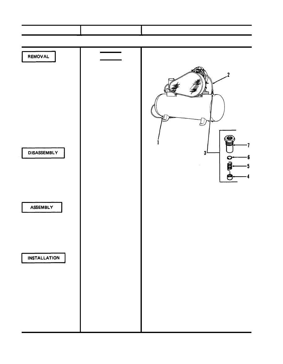
4-46. CHECK VALVE lNSPECTION/REMOVAL/DISASSEMBLY/ASSEMBLY/lNSTALLATION - continued
WARNING
Air pressure in tank must be
discharged before removal of
check valve. Removal under
pressure could cause serious
injury.
1. Main power
Disconnect.
Open to discharge all air in
2. Drain cock (1)
tank.
Disconnect from check valve.
3. Aftercooler (2)
Remove by unscrewing from
4. Check valve (3)
tank.
1. Cage (4)
Remove by unscrewing
from body (7).
2. Spring (5)
Remove.
3. Disk (6)
Remove.
Figure 4-85. Check valve replace
Install.
1. Disk (6)
Install and hold in position.
2. Spring (5)
Screw into body (7) and
3. Cage (4)
tighten.
Close.
1. Drain cock (1)
Be careful not to strip threads.
Install in tank and tighten.
2. Check valve (3)
Connect to check valve and
3. Aftercooler (2)
tighten.
Connect.
4. Main power
4-76

