
TM 5-4310-373-14
5-2. COMPRESSOR/ASSEMBLY
This task covers:
The assembly of the compressor.
INITIAL SETUP
Equipment Condition:
Tools:
Compressor removed and disassembled
Materials/Parts:
Gasket 5330-00-450-4130
Sealant
Oil OE-30
Approximate Time Required (minutes):
Personnel Required:
60
1 Mechanic
REMARKS
ACTION
LOCATION/TIME
NOTE
Oil gage is to be replaced only
if it was noted to be defective
See para 5-1.
in disassambIy procedure.
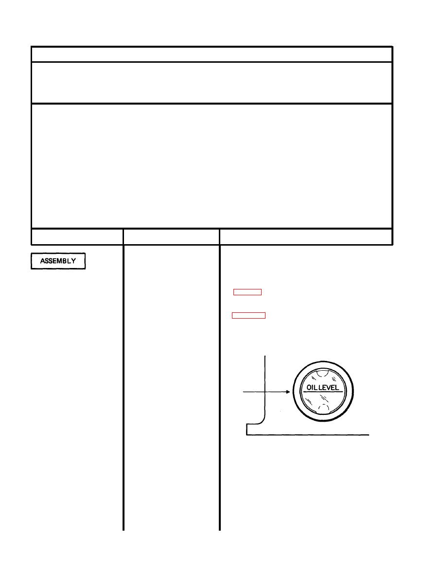
1. Oil gage (1)
Indicating mark on gage must be horizontal to crankcase.
Coat edges with sealant and
See Figure 5-3.
press into crankcase with a
block of wood.
Install.
2. Plug (2)
Install.
3. Pipe (3)
Install.
4. Cap (4)
Install.
5. Plug (5)
Figure 5-2. Oil level gage
5-6

