• Home
  • Download PDF
  • Order CD-ROM
  • Order in Print
Figure 3-15. Drive Pulley, Removal. - TM-5-4310-377-130055
Section VIII. MAINTENANCE OF COMPRESSOR ASSEMBLY - TM-5-4310-377-130057

TM-5-4310-377-13 Compressor Unit Reciprocating 5 CFM 175 PSI Electric Motor Driven Model:E23CV7A Manual
Page Navigation
  45    46    47    48    49  50  51    52    53    54    55  
TM 5-4310-377-13
3-15. DRIVE PULLEY - Continued.
c. Inspection.
(1) Inspect for missing or damaged hardware.
(2) Inspect bushing for damage.
(3) Inspect pulley for damage.
d. Repair. Repair of the drive pulley is limited to the replacement of defective components at the Unit Maintenance
level.
e. Installation. (Refer to Figure 3-16).
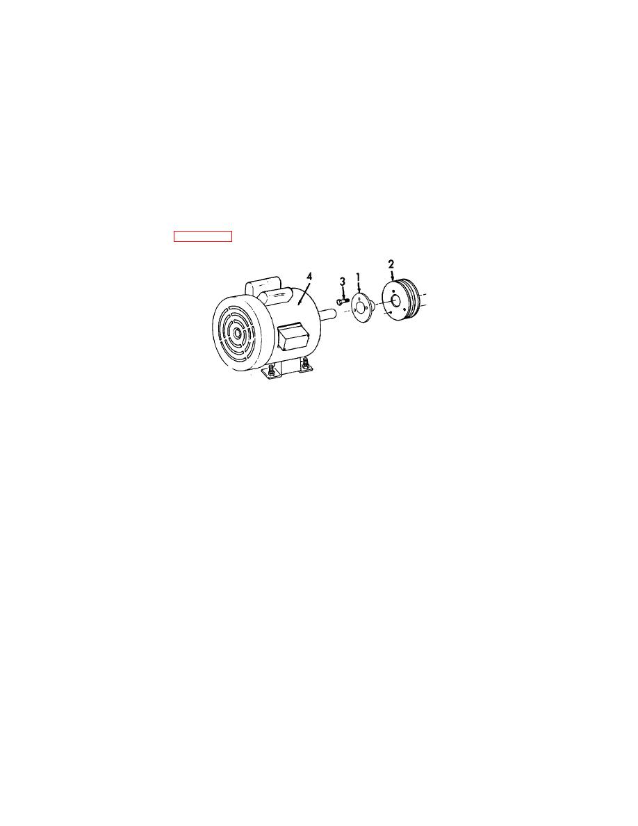
Figure 3-16. Drive Pulley, Installation.
(1) Attach bushing (1), to pulley (2) with three bolts (3).
(2) Install pulley (2) on motor (4).
END OF TASK
3-36


Western Governors University

Privacy Statement
Press Release
Contact

© Copyright Integrated Publishing, Inc.. All Rights Reserved. Design by Strategico.