
TM 5-4310-382-13
3-30. OIL FILLER CAP, PLUG, AND DRAIN.
This task covers:
a. Removal
b. Cleaning
c. Inspection
d. Installation
INITIAL SETUP
Tools Required
Tool Kit, General Mechanic's
Materials Required
Brush, Medium Bristle (item 4, Appendix E)
Solvent, Dry Cleaning (item 2, Appendix E)
Cloth, Lint-Free (item 3, Appendix E)
Compound, Anti-seize (item 7, Appendix E)
Equipment Condition
Engine shut down and cool.
Oil drained from compressor unit (see para 3-2).
a. Removal.
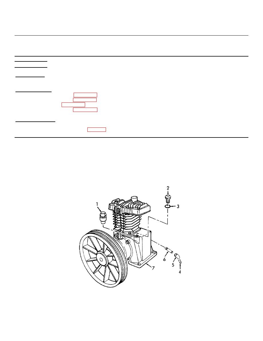
(1) Remove plug (4), elbow (5), and nipple (6) from compressor crankcase (7).
(2) Remove cap (2) and o-ring (3) from crankcase (7).
(3) Remove cap (1) from crankcase (7).
Figure 3-32. Oil Filler Cap, Plug and Drain, Removal.
3-67

