TM 5-4310-385-13
CHAPTER 2. OPERATING INSTRUCTIONS
SECTION I. DESCRIPTION AND USE OF OPERATOR'S CONTROLS AND INDICATORS
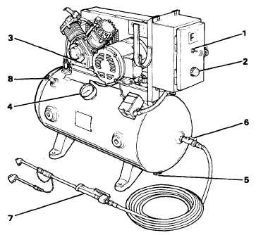
2-1. OPERATOR'S CONTROLS AND INDICATORS.
Key
Name
Location
Function
On
Location
Main power switch
Main switch box
Turns electric power to the compressor on
and off.
1
ON/OFF switch
Starter enclosure
Start and stop compressor.
2
RESET button
Starter enclosure
Push to reset after overload condition has
tripped the protective relay on magnetic
starter.
3
Oil level sight
Compressor crankcase
Shows oil level in crankcase.
glass
4
Pressure gage
Air tank
Shows air pressure in tank.
5
Drain cock
Bottom of air tank
To drain air and water from tank.
6
Shutoff valve
End of tank
To close off air tank when air hose has to
be removed.
7
Inflator gage
End of hose
To pressurize pneumatic equipment and read air
pressure.
8
Safety relief valve
Air tank
Releases air pressure in tank above 200 psi.
Can be manually checked by pulling ring.
Operator's Controls and Indicators
2-1