TM 5-4310-389-14
Figure 3-43. Grease Fittings
NOTE
A new clutch generally requires several adjustments until the friction surfaces are worn in. Do not let
the clutch slip as this may damage friction plates.
NOTE
A common indication that the friction surface is worn out is that the adjusting ring cannot be further
tightened.
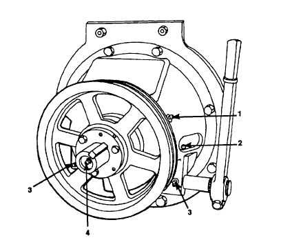
ADJUST
a.
To adjust the clutch, remove the inspection cover plate in the housing and rotate the clutch until the adjusting lock
and lock screw can be reached. Remove the bolt and the adjusting lock. Turn the adjusting ring counterclockwise
to obtain recommended operating lever pressure.
b.
Reinstall the adjusting lock and bolt.
c.
Reinstall the inspection cover plate.
3-75