TM-5-4310-389-14
INSPECT
b.
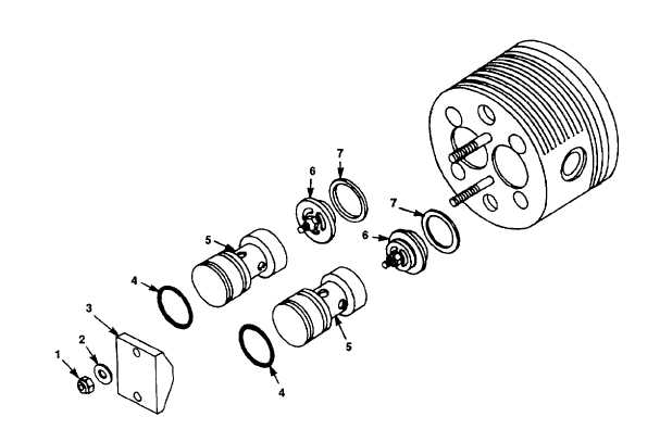
Changing the valves of 2nd and 3rd stage. Refer to figure 4-5.
1.
Loosen and remove the hex head nuts (1) and washers (2); remove cap holder (3).
2.
Insert two screwdrivers into the groove of the valve cap (5) and lift off valve cap with 0-ring (4).
3.
Check 0-ring (4) and replace, if required.
4.
Withdraw valve (6); remove gasket (7) and discard.
5.
Check valve (6) and replace, if required.
Figure 4-5. Valve Head, 2nd and 3rd Stage
4-29