TM-5-4310-389-14
INSPECT
a.
If the cylinder is renewed, a new piston must be fitted. Normal sizes and oversizes are given in the specifications
table.
b.
Inspect the piston, including the bosses, for damage or visible wear. Inspect the area above the top ring. If the
grooves cannot be felt on any part of the piston, replace the piston.
c.
Remove the compression rings and oil control ring using piston ring expander No. 003-0496 (figure 4-24).
Inspect the ring lands for damage or wear.
d.
Open and remove the expander spring for the oil control ring.
e.
Clean the piston ring grooves.
f.
Measure axial piston ring clearance using commercial tools.
NOTE
If, when measuring a piston with trapezoidal ring groove, a gap is found to exist between the inserted gauge and
the piston, this indicates that the axial piston ring clearance is within the tolerances stated in the specification
data in table 4-4 and the piston is fit for further use.
g.
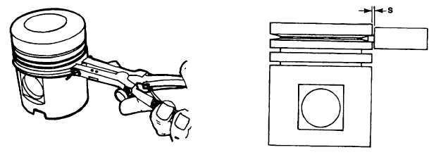
Measure first piston ring groove, if trapezoidal, by means of trapezoidal groove wear gauge No. 003-0438. Note
gap S (figure 4-25).
h.
If the gauge contacts the side of the piston (without gap), the piston must be renewed.
i.
Insert all the piston rings singly in the cylinder and press down with the piston to a distance of 30 mm from the
cylinder head contacting surface. Measure the gap clearance of the piston ring.
Figure 4-24. Removing Piston Rings
Figure 4-25. Axial Clearance for
Trapezoidal Piston Ring
4-54