TM-5-4310-389-14
24.
Insert the two push rod sheaths, spring end first, in the tappet bore in the crankcase and locate the upper
end with the gasket in the cone of the cylinder head. Remove the spring tensioner.
25.
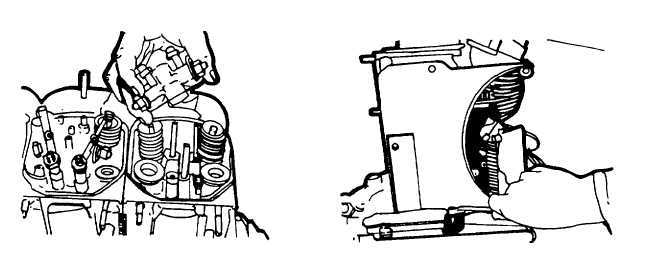
Assemble the push rods and mount the rocker arm shaft support (figure 5-46). i 26.
Adjust
the valve clearance and decompressors (refer to 3-22).
27.
Place new gasket with sealing compound to rocker chamber cover. Position cover, align, and fit bolt with
new washer. See specification data tightening, table F-1.
28.
Install injector guide and injector with new washer in cylinder head. Tighten bolts as under specification
data. Install thrust piece and place injector clamp in position. Place washer with convex side facing stirrup
and screw on nut, and torque. Refer to Appendix F.
n.
Reassemble the Engine.
1.
Coat a new gasket with grease and place it in position on the injection pump cover. Rotate the camshaft
so that the cams that operate the pumping elements face toward the casing. Mount the injection pump
cover, ensure the gears are in mesh.
2.
Connect the breather pipe and install in the injection pump with gasket sealing compound. Assemble the
oil dipstick fitted with a new rubber 0-seal.
3.
Assemble the front vertical plate (figure 5-47).
Figure 5-46. Installing Push Rods/
Figure 5-47. Assembling Front Vertical
Mount Rocker Arm Shaft Support
Plate
5-28