TM-5-4310-389-14
5-10
TIMING GEARS (ENGINE)
DESCRIPTION
This task covers: Replace. Repair.
INITIAL SETUP
Tools:
Equipment conditions:
Screwdriver, metric feeler gauge
The engine must be cold.
Materials/parts:
Cloth, Lint-free, item 9 Appendix E
REPLACE REPAIR
NOTE
Do not change the setting of oil nozzle unless required. With hot engine running at idling, an oil flow
to pad of rocker arm must be just noticeable. An excessive oil flow can lead to higher oil
consumption.
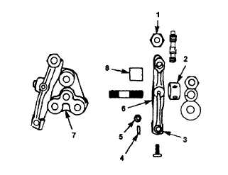
a.
Overhauling the Rocker Arm Bracket.
1.
Ensure rod ends are tightly seated and free from wear (figure 5-82).
Figure 5-82. Push Rod, Push Rod Tube, and Tappet
5-52