TM 5-4310-393-14
5-6.1.
ENGINE FLYWHEEL.
This task covers: A. Inspect B. Replace
Tools:
Materials/Parts:
Shop Set, Automotive Field
Diesel Fuel Oil NSN 9140-00-286-5294
Maintenance, Basic
Equipment Conditions:
Socket, 61209900
Engine Secured and Cooled
A.
Inspect.
1.
Removing the Flywheel Assembly.
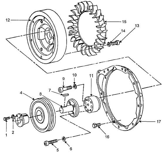
FIGURE 5-1. ENGINE FLYWHEEL/IMPELLER ASSEMBLY
a.
Remove three hex head cap screws (Figure 5-1, Item 1) and lock washers (2) from split taper bushing (3).
b.
Remove bushing (3) and groove pulley (4).
c.
Remove four socket head cap screws (5) and washers (6) from the stub shaft (8).
d.
Remove stub shaft (8). Be sure not to misplace stub shaft key (7).
5-6