TM 5-4310-393-14
WARNING
DEATH OR SERIOUS INJURY COULD OCCUR IF COMPRESSED AIR IS DIRECTED
AGAINST THE SKIN. DO NOT USE COMPRESSED AIR FOR CLEANING OR
DRYING UNLESS THE PRESSURE HAS BEEN REDUCED TO 30 PSI (2.06 BAR) OR
LESS. WHEN WORKING WITH COMPRESSED AIR ALWAYS USE CHIP GUARDS,
EYE PROTECTION, AND OTHER PERSONAL EQUIPMENT.
a.
Clean all parts in a shop parts washer if available, or with a clean cloth dampened with diesel fuel oil.
Use wire brush where necessary. Dry with low pressure compressed air.
C
Inspect.
1.
Inspecting the Parts.
a.
Inspect all parts for cracks, rust,
corrosion, and excessive heat damage.
b.
Inspect
for
accumulated
carbon
around injector seat In cylinder head.
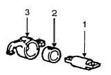
FIGURE 5-21. ROCKER ASSEMBLY
c.
Measure rocker shaft (Figure 5-21, Item 1) diameter. If rocker shaft diameter is smaller than 0 7074
inch (17 974 mm), it must be replaced.
d.
Measure rocker bore bushing (2) inside diameter. If rocker bushing bore is greater than 0.7084 inch
(17 994 mm) replace bushing (2).
e.
Measure rocker (3) radius The radius must be 0.315 inch (8 mm). No flattening or brinnelling is
permitted on the rocker radius. If there is evidence of flattening, the rocker must be replaced
NOTE
When replacing the rocker (3) you must also replace the bushing (2). They are re-
placed as a set. The bushing (2), however, can be replaced separately.
2.
Inspecting the Valve Seats. Check valves, valve seats, and valve guides as follows:
a.
Check that the inside diameter of
each valve guide does not exceed 0 278 inch (7 059
mm).
b.
Check that the valve seat angle
does not exceed 45 degrees.
c.
Clean valves with diesel fuel and
wire brush and dry with low pressure compressed air.
d.
Inspect valves for warping, burning,
or other damage.
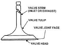
FIGURE 5-22. VALVE ELEMENTS
e.
Inspect valve tulips, faces, and heads for pitting, ridges, or cracks
f.
Check that each valve stem diameter is not less than 0.2736 in (6 95 mm).
5-20