TM 5-4310-393-14
WARNING
DEATH OR SERIOUS INJURY COULD OCCUR IF COMPRESSED AIR IS DIRECTED
AGAINST THE SKIN. DO NOT USE COMPRESSED AIR FOR CLEANING OR
DRYING UNLESS THE PRESSURE HAS BEEN REDUCED TO 30 PSI (2.06 BAR) OR
LESS. WHEN WORKING WITH COMPRESSED AIR ALWAYS USE CHIP GUARDS,
EYE PROTECTION, AND OTHER PERSONAL EQUIPMENT.
a.
Clean connecting rod components with dry cleaning solvent. Remove any carbon deposits with a
wire brush. Clean inside surface of rod bushing (Figure 5-46, Item 9), both connecting rod halves (6 and 7), and bearing
(8). Blow compressed air through the drilled oil passage in connecting rod to clean connecting rod and rod bushing.
b.
Visually inspect, connecting rod for bending, warping, cracking, rust, or other damage Check for
cracks using MIL-1-6868 magnetic particle inspection Replace if twisted or bent Replace if indications of cracks are
revealed by magnetic particle Inspection.
c.
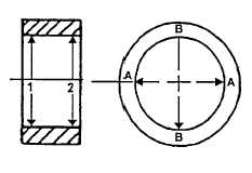
Measure and record rod bushing (9) inside diameter. Measure at points 1 and 2 along axis A and B
(see Figure 5-47). Measurements should be 0 9850 to 0.9856 inch (25 020 to 25 033 mm) If any measurement is outside
these limits, replace rod bushing.
d.
Inspect upper and lower bearing halves (Figure 5-46, Item 8) for excessive wear, scoring, pitting,
flaking, etching, and signs of overheating Inspect bearing backs for bright spots (bearing moving in supports).
e.
Apply some oil to contact surfaces
and temporarily assemble connecting rod with two new
socket head cap screws and without bearings Coat the
threads of the screws with oil Using a torque wrench,
tighten screws to 29 50 Ib.-ft (40 Nm).
f.
Measure
inside
diameter
of
connecting rod bearing bore. Measurement should be
1.8114 to 1.8108 inches (46.010 to 45 994 mm). If
measurement
is
outside
specified
limits,
replace
connecting rod.
FIGURE 5-47. MEASUREMENT POINTS
g.
Disassemble connecting rod carefully and insert bearing halves (8) The bottom half has a hole which
matches with the connecting rod cap Reassemble connecting rod with two socket head cap screws. Tighten screws
following procedures described in preceding step 5.
h.
Measure inside diameter of bearing. Measure at points 1 and 2 along axis A and B. Measurements
should be 1.6538 to 1.6529 inches (42 006 to 41 986 mm).
i.
If any measurement is outside the tolerance limits, replace the bearing. Make sure that
measurements for points 1 and 2 are not different or outside the tolerance limits, indicating that bearing is wearing in a
conical shape.
j.
Make sure measurements along axis A and B are not different or outside tolerance limits, indicating
bearing is wearing in an oval shape.
k.
If bearing is out-of-round, replace it. Follow procedure described in paragraph 5-6.12. Also check
cylinder and piston for unusual wear. Follow procedures described in paragraphs 5-6.5 and 5-6.6
5-37