TM 5-4310-451-14
5-49. EXHAUST VALVE CLEARANCE ADJUSTMENT.
This Task Covers: Clearance Adjustment
Initial Setup:
Equipment Conditions:
Tools/Test Equipment:
• Engine cool.
•
General mechanic's tool kit
• Rocker arm covers removed (see paragraph 429).
CLEARANCE ADJUSTMENT
1. Place ON/OFF engine switch in OFF position (see paragraph 2-12)
NOTE
• Perform steps 2 through 7 at each of six cyl-
Inders.
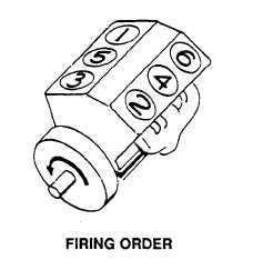
• All exhaust valve clearances may be adjusted
during one full revolution of crankshaft. Refer to
Illustration for firing order.
2.
Using engine starter, rotate crankshaft until injector (1) is fully depressed.
CAUTION
Exhaust valve clearance is adjusted at pushrod. DO NOT disturb exhaust valve bridge adjusting screw or
damage to engine could occur.
3.
Loosen pushrod locknut (3).
4.
Insert 0.017 in. (0.432 mm) feeler gage between top of exhaust valve bridge (4) and rocker arm (5).
TA705039
5-164